03.05.2026 by Viktor Siebert
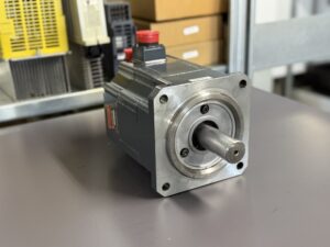
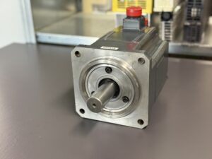
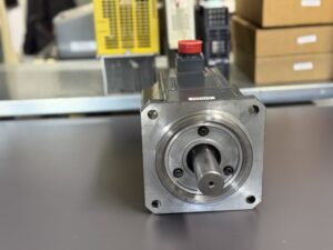
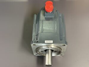
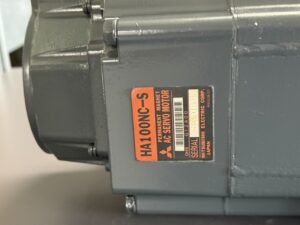
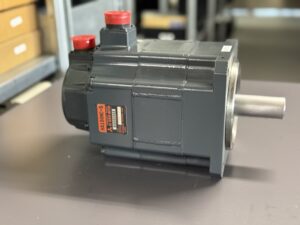
Repair of a Mitsubishi HA100NC-S Servo Motor with Encoder Fault Alarm 5A on MDS-B-SVJ2-06
Initial situation and fault description,
The Mitsubishi HA100NC-S servo motor was operating together with the servo drive MDS-B-SVJ2-06 and showed increasing disturbances over time. The reported fault was alarm 5A, which corresponds to Collision Detection 2. This alarm is triggered when the commanded torque reaches the maximum allowable value.
What was noticeable was the gradual progression. Initially, the fault appeared only sporadically, about once per week. Over time, the frequency increased significantly, first daily and eventually approximately every 20 minutes. This clearly indicates that it was not a sudden electrical failure, but rather a progressive degradation within the system.
The machine could no longer be operated reliably. Particularly critical was that the fault occurred under load as well as during normal movements, without any clear relation to operator actions.
Incoming inspection and initial diagnosis
During incoming inspection, the basic electrical functionality was checked first. Insulation measurement of the motor was within normal range. The winding and power section showed no abnormalities.
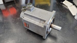
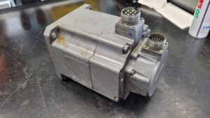
The focus quickly shifted to the feedback system, as the fault progression is typical for signal-related issues. The encoder was a Mitsubishi OSE104 or comparable variants such as OSA105 or OSE253.
Even at standstill, slight inconsistencies in the feedback signal were detected. Under motion, these effects became more pronounced. The signal quality was not stable, leading to incorrect position and torque values.
Technical analysis
Alarm 5A occurs when the drive requests maximum torque because the control system assumes that the axis is blocked or a collision has occurred.
In this case, the root cause was not mechanical but related to feedback:
Cause
Wear and aging of the encoder
Effect
Incorrect position and speed feedback
Result
Control deviation in the servo system
Symptom
Drive interprets the situation as a collision and triggers alarm 5A
Typical for these encoders is a gradual degradation of signal quality due to:
- aging of optical components
- contamination or moisture ingress
- mechanical play in the encoder section
This leads to sporadic signal errors, which can initially be compensated but eventually cause significant control deviations.
Repair measures and overhaul
The motor was completely disassembled and technically overhauled.
Work performed:
- complete disassembly of the motor
- cleaning of all assemblies
- inspection of winding and insulation
- replacement of bearings
- overhaul of the OSE104 encoder
The encoder was not simply replaced but specifically refurbished. This included:
- cleaning of optical elements
- reconditioning of signal structure
- verification of pulse quality
- calibration of the feedback system
Additionally, preventive measures were implemented:
- improved sealing
- inspection of mechanical fits
- repair of connectors and contacts
Final functional test
After overhaul, the motor was tested on a test bench.
Test procedure:
- power-on behavior
- operation at low speed
- operation at medium speed
- operation at high speed
- load simulation
Special focus was placed on:
- encoder signal stability
- consistent torque behavior
- thermal performance
The motor ran stable across all speed ranges. No signal drops. No alarms.
Conclusion
The fault was not a classic mechanical failure but a typical aging issue within the encoder. The gradual progression was critical, as the motor continued to operate for a long time despite the degradation.
The encoder overhaul was decisive. Without stable feedback, proper control is not possible.
After refurbishment, the motor is fully reliable again. The combination of mechanical overhaul and encoder repair ensures a sustainable solution.
More details about our Mitsubishi repair services can be found here:
Mitsubishi motor Repair by Industrypart
📞 Feel free to contact us with any questions about your Mitsubishi drive technology.
Our expert team is happy to help!
Technical Specifications
Motor
| Parameter | Value |
|---|
| Manufacturer | Mitsubishi |
| Device type | AC Servo Motor |
| Model designation | HA100NC-S |
| Series | Melservo / NC series |
| Power | approx. 1.0–1.5 kW |
| Input voltage | 200 V AC |
| Output voltage | controlled by drive |
| Rated current | approx. 6–10 A |
| Control type | servo control |
| Feedback | incremental encoder OSE104 |
| Cooling | self-cooled |
| Protection class | IP55 |
| Ambient temperature | 0 to 40 °C |
| Mounting | flange |
| Origin | Japan |
| Product status | discontinued / available |
Drive
| Parameter | Value |
|---|
| Manufacturer | Mitsubishi |
| Device type | Servo Drive |
| Model designation | MDS-B-SVJ2-06 |
| Series | MDS-B |
| Power | approx. 0.6–1.5 kW |
| Input voltage | 3x 200 V |
| Output voltage | PWM controlled |
| Rated current | approx. 6 A |
| Control type | CNC servo |
| Feedback | motor encoder |
| Cooling | fan |
| Protection class | control cabinet |
| Ambient temperature | up to 55 °C |
| Mounting | control cabinet |
| Origin | Japan |
| Product status | available / service |
Operating environment and applications
Typical machines:
- CNC machining centers
- lathes
- machine tools
Typical years:
Typical applications:
- feed drives
- positioning axes
- tool movements
Important requirements:
- stable ambient temperature
- clean supply voltage
- proper shielding of encoder cables
Critical factors:
- thermal load in control cabinet
- EMC influence on signal lines
Functional description
The system consists of servo motor, drive and encoder.
Basic function:
The drive generates a controlled voltage for the motor. The encoder provides position and speed feedback.
Interaction:
- power stage generates motor current
- control compares setpoint and actual value
- encoder delivers actual value
Protection functions:
- overcurrent
- overload
- overvoltage
- collision monitoring
Collision monitoring is safety-relevant. It prevents mechanical damage in case of blockage or malfunction.
Alarm messages and troubleshooting
| Alarm code | Description | Possible cause | Recommended action |
|---|
| 10 | Undervoltage | power supply issue | check supply |
| 13 | Software error | CPU issue | check drive |
| 17 | A/D error | measurement fault | check electronics |
| 18 | Encoder init error | cable or encoder faulty | check connection |
| 2B | Encoder CPU error | encoder faulty | replace encoder |
| 2D | Encoder data error | signal disturbance | check wiring |
| 2F | Encoder communication | cable or noise | check shielding |
| 30 | Regeneration | resistor overload | check resistor |
| 31 | Overspeed | control issue | check parameters |
| 32 | Overcurrent | motor or cable | check insulation |
| 33 | Overvoltage | supply or braking | check supply |
| 3A | Motor overcurrent | wrong tuning | check parameters |
| 46 | Motor overheat | overload | check cooling |
| 50 | Overload | mechanical load | check load |
| 5A | Collision detection 2 | max torque reached | check mechanics or encoder |
Assembly overview
| Assembly | Functional name | Function | Notes |
|---|
| Power stage | output stage | motor control | check thermal condition |
| Control unit | control board | setpoint comparison | sensitive to noise |
| Encoder | feedback system | position signal | common failure source |
| Bearings | mechanical support | smooth rotation | wear part |
| Connections | connectors | signal transmission | check contacts |
| Housing | enclosure | environmental protection | check sealing |