25.07.2025 by Viktor Siebert
Story. Our repair and test process MDS-C1-SPH-55 Mitsubishi Spindle Drive Unit
A customer brought in an MDS‑C1‑SPH‑55 spindle drive that had already been overhauled by another service provider. The previous workshop had replaced some components, but had no suitable test bench. Therefore it could only repair the amplifier “on suspicion” and not test it under load. After installation in the machine an overload fault still occurred during rapid traverse. The customer was frustrated and turned to us on recommendation.
Our repair began with a thorough incoming inspection:
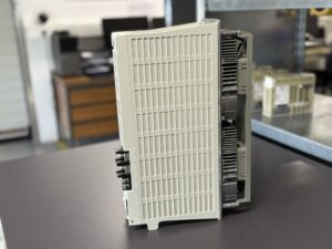
- Disassembly and visual inspection. The housing was opened to inspect boards, capacitors, connectors and solder joints. Depending on their condition we replaced aged DC‑link capacitors, buffer capacitors and IGBT modules. Fans and heatsinks were cleaned or renewed.
- Electrical tests. We checked the DC‑link capacitors for capacitance loss and ESR, the IGBT modules for short circuits and the driver boards and current sensors with a multimeter. Coils and relays were measured.
This was followed by the test phase on our own test bench, which simulates the real environment of a CNC machine. We simulated bus control signals and tested the functions POT/NOT (positive/negative over‑current shutdown), encoder feedback, speed control and power consumption. Under full load we monitored current, voltage and temperature and subjected the drive to the nominal load for a long period to observe thermal effects. We also checked and calibrated all parameters specified by the controller.
The repaired drive passed all tests without error messages. After final testing the unit was handed over to the customer and installed in his machine. For three weeks now the spindle drive has been running smoothly in production, the overload alarm has disappeared. Our structured approach, which includes both preventive overhaul and realistic load testing, enabled us to solve the problem once and for all. The customer was satisfied and entrusted us with further devices.
Conclusion
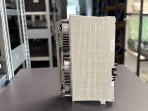
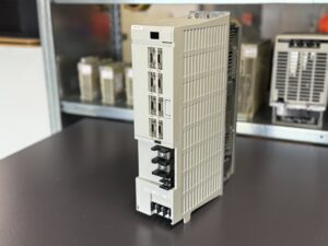
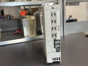
The MDS‑C1‑SPH‑55 is a powerful spindle amplifier that supplies a 5.5 kW AC spindle motor in CNC machines. Its electronic structure generates a variable frequency of 0 to 833 Hz at an output voltage of 200 V. Thanks to its compact design and improved cooling fins the device is suitable for narrow control cabinets; at the same time it requires good ventilation and a clean, dry operation. Many alarms can be avoided through correct parameterisation, intact motor and encoder cables and regular maintenance. Critical components such as IGBT modules, electrolytic capacitors and fans should be renewed preventively after a few years.
The case study shows that a repair without suitable test facilities rarely succeeds. Our systematic repair process, consisting of visual and electrical inspection, replacement of wear parts, parameter correction and comprehensive load tests, led to a lasting result. Since the overhaul the spindle drive has been operating reliably. This underscores the importance of professional diagnosis and load testing when repairing electronic drive technology.
To mentioned Mitsubishi Drive: Mitsubishi MDS-C1-SPH-55 oder MDSC1SPH-55 Spindle Drive Unit
Similar type MDS-C1-SPHx-55
More details about our Mitsubishi repair services can be found here:
Mitsubishi drive Repair by Industrypart
📞 Feel free to contact us with any questions about your Mitsubishi drive technology.
Our expert team is happy to help!
Technical Summary of the Unit
| Parameter | Typical value |
|---|
| Device class | Spindle amplifier / spindle controller of the MDS‑C1 series; model MDS‑C1‑SPH‑55 |
| Output frequency (range) | 0 – 833 Hz (VFD for driving the AC spindle motor) |
| Output voltage | 3‑phase output 200 V AC |
| Maximum output power / current | 5.5 kW (rated current ~18 A) |
| Input voltage | DC 270‑311 V (via DC link) / AC 200 – 230 V (control voltage); input current 20 A (control current 0.2 A) |
| Input frequency | 50/60 Hz |
| Phases | 3‑phase input and output |
| Efficiency and heat dissipation | During continuous rated operation approx. 190 W of heat is produced; therefore clearance must be left above and below the device. |
| Weight | approx. 7.0 kg |
| Recommended environment | Operation at 0 – +40 °C (no frost), relative humidity up to 80 % (no condensation); storage –15 °C to +70 °C, max. 90 % RH; installation indoors with no direct sunlight, no corrosive gases, oil mist or dust and up to 1000 m above sea level |
| Installation notes | The spindle amplifier must be mounted next to the appropriate MDS‑C1 power supply; sufficient air space must be kept because each unit generates heat. |
Alarm messages and troubleshooting
The spindle amplifiers are equipped with extensive self‑monitoring. If a fault occurs, alarm signals with numbers are displayed. The following table summarises typical alarms – based on the EU‑Repair page, the master alarm list and the Precision Zone fault analysis and lists possible causes and approaches to rectification.
| Alarm number (display) | Meaning / possible fault | Troubleshooting (summary) |
|---|
| A.32 (SP 32) | Overcurrent in the power module – the motor current exceeds the allowable value | Disconnect motor leads and check for short circuit; measure the motor insulation with a megohmmeter; then test the drive without the motor. If the alarm persists this indicates an internal fault in the power module |
| A.3A (SP 3A) | Overcurrent/overload in the motor – temporarily excessive current or blocked spindle | Is the motor blocked? Check the spindle mechanics; check motor current parameters; if the error occurs repeatedly, examine motor windings for damage |
| A.3B (SP 3B) | Overheating of the power module | Clean fans and heatsink; check whether ventilation is blocked; if the temperature sensor is defective, replace the module |
| A.52 (SP 52) | Regulation error too large – the difference between reference and actual value is outside the permissible range | Check parameters (e.g. speed control loop); inspect encoder cables and connectors; reduce motor load |
| Axis‑Selection Error (SV 4X) | Wrong axis or missing axis selection | Program the correct axis number; check cables/connectors |
| Memory Error 1/2 (SV 5B/5C) | Defect in internal memory or software processing | Save parameters; perform a reset; if the message reappears the board must be repaired or replaced |
| Software Processing Error (SV 68) | Faulty software processing / A‑D converter error | Check NC programs; if not correctable, a hardware fault is likely; the device must be repaired |
| Magnetic‑Pole Detection Error | Problems with pole detection (encoder error) | Check encoder cables and connectors; check parameter SP025 (number of poles); recalibrate the motor |
| Undervoltage (SP SV) | PN bus voltage below 200 V | Check mains voltage; measure rectifier and DC‑link capacitors; replace defective components |
| Overload / vibration | Device reports overload during rapid traverse or shows strong vibration | Check motor connector/cable for insulation faults; run the spindle motor in jog mode to identify mechanical blockages; if overload occurs, disconnect consumers step by step to locate defective assemblies |