08.11.2026 by Viktor Siebert
Mitsubishi MDS-B-CVE-370: Fan stopped – inspection and overhaul
The cooling fan on a Mitsubishi MDS-B-CVE-370 has stopped, yet the power supply still starts? Functional testing and condition assessment should then be considered separately. This guide explains the role of the Power Supply Unit, how to approach a stopped fan and why a successful trial run does not establish good maintenance condition. A documented workshop example illustrates the subsequent overhaul and checks.
Role and applications of the MDS-B-CVE-370
This supply module forms part of a compatible Mitsubishi CNC drive system. It supplies the DC link for the connected servo and spindle amplifiers. Those amplifiers control the motors, while the CNC provides movement commands. Applications include machine tools with feed axes and a main spindle.
Replacement selection depends on the complete model designation, supply ratings, connected amplifiers and machine documentation. Similar connections or model numbers alone do not establish interchangeability.
Technical data
| Item | Specification |
|---|
| Manufacturer | Mitsubishi Electric |
| Model | MDS-B-CVE-370 |
| Device type | Power Supply Unit |
| Main input, nameplate | 3 AC 200 V / 200–230 V; 50/60 Hz; 121 A |
| Auxiliary input, nameplate | AC 200 V / 200–230 V; 50/60 Hz; 0.2 A |
| Output, nameplate | DC 270–311 V; 164 A |
| Manual reference on nameplate | BNP-B3759 |
These electrical ratings come from the original nameplate. They are not measurements taken during our test.
Symptom: stopped fan while the power supply operates
A power supply can pass a functional test while its cooling or maintenance condition still requires attention. Fan operation, air passages and contamination therefore belong in the assessment. A stopped fan is initially an observation. Mechanical obstruction, an electrical fault in the fan supply or another cause must be distinguished by checking the actual unit. Operating conditions and manufacturer instructions must be considered.
A fan finding does not establish the cause of a previous machine alarm. A brief trial run also cannot cover every operating condition. Any additional shutdowns or messages must be recorded and investigated separately.
Troubleshooting: useful information and checks
Start by recording the complete model designation and displays. Note whether the symptom occurs at power-up, at rest or during movement. Photograph any CNC message and the power supply indication before resetting. Cold and warm behaviour, as well as previous changes, also help guide diagnosis.
A qualified inspection then distinguishes the mechanical condition of the fan from its electrical supply and the rest of the cooling path. Contaminated air passages and cabinet filters also need assessment. Only qualified personnel should work inside the unit, following manufacturer procedures. Isolate the supply, prevent reconnection, observe discharge times and verify the absence of voltage.
The alarm reference below helps identify indications. An alarm code alone does not diagnose a particular failed component. Without a clear message, observed behaviour and recorded test conditions remain essential.
Workshop example: findings and preventive overhaul
An MDS-B-CVE-370 examined in our workshop powered up and passed its initial spindle test. However, condition inspection found heavy contamination and a dirty, seized fan that did not rotate. No alarm code was documented for this example.
After approval, the unit was cleaned and preventively overhauled. Final checks confirmed satisfactory spindle testing, display operation and fan operation. The rotary switch was returned to its original setting. The photos and video show this workshop example.
Final inspection results
| Recorded final check | Result |
|---|
| Spindle test | Okay |
| Display | Okay |
| Cooling fan | Okay |
| Rotary switch | Returned to its original setting |
Prevention: assess condition as well as function
Inspect air passages, cabinet filters and fan operation as part of the prescribed maintenance routine. Inspection intervals should suit the machine and its actual exposure to dust or oil mist. Record abnormalities so that changes in condition can be identified.
Both operating behaviour and physical condition matter when deciding whether an overhaul is appropriate. The workshop example demonstrates that a satisfactory incoming test does not replace condition inspection.
Sources
Workshop records and original media for repair 108246-1; original nameplate. Technical reference: Mitsubishi MDS-A, MDS-B & MDS-C1 Maintenance Manual, section II, printed pages II-3 and II-16. This manufacturer document provides general technical context, not evidence that an alarm occurred in this case.
Test-bench video
Photos before and after overhaul
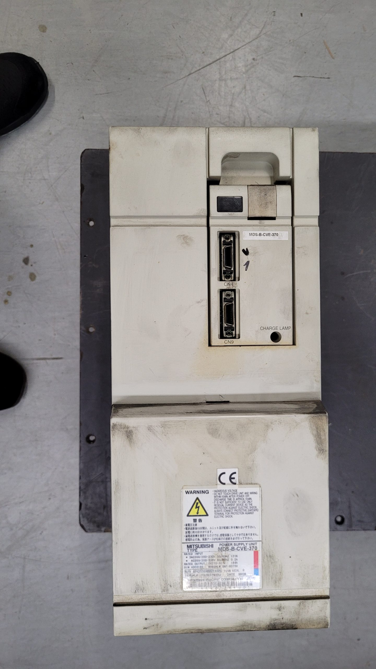 Before overhaul: overall view with original nameplate
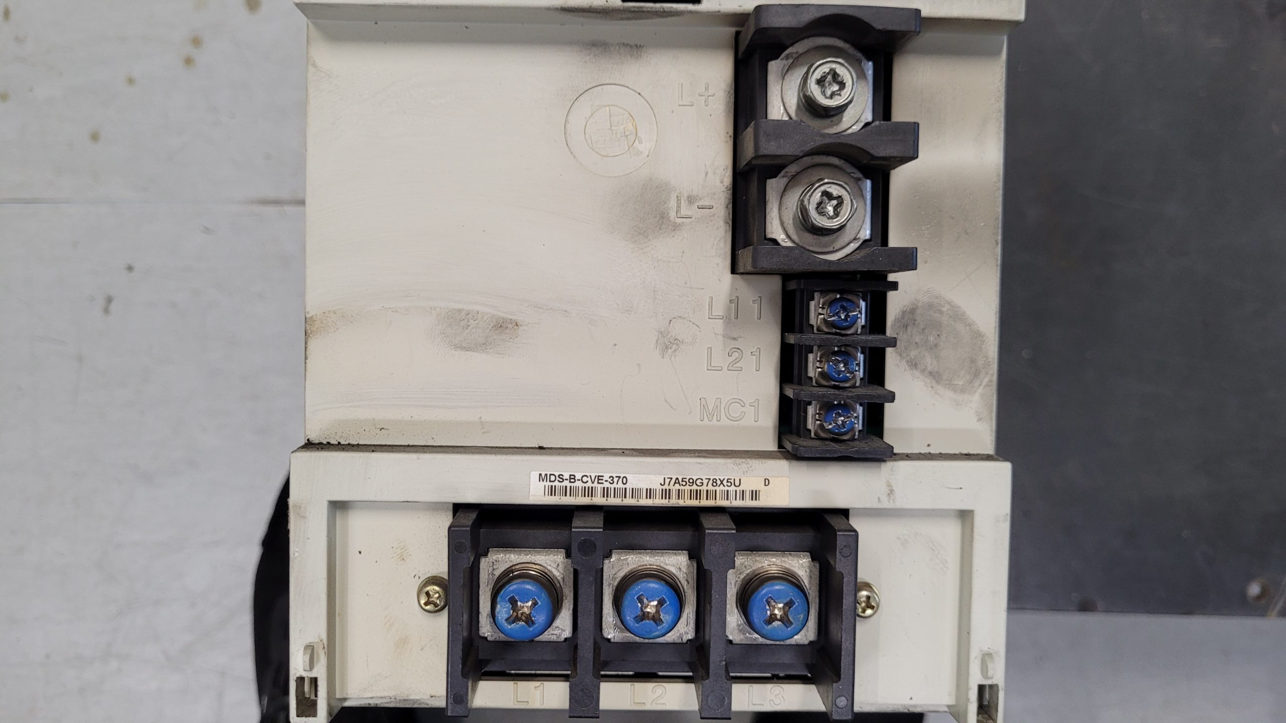 Before overhaul: connections and model identification
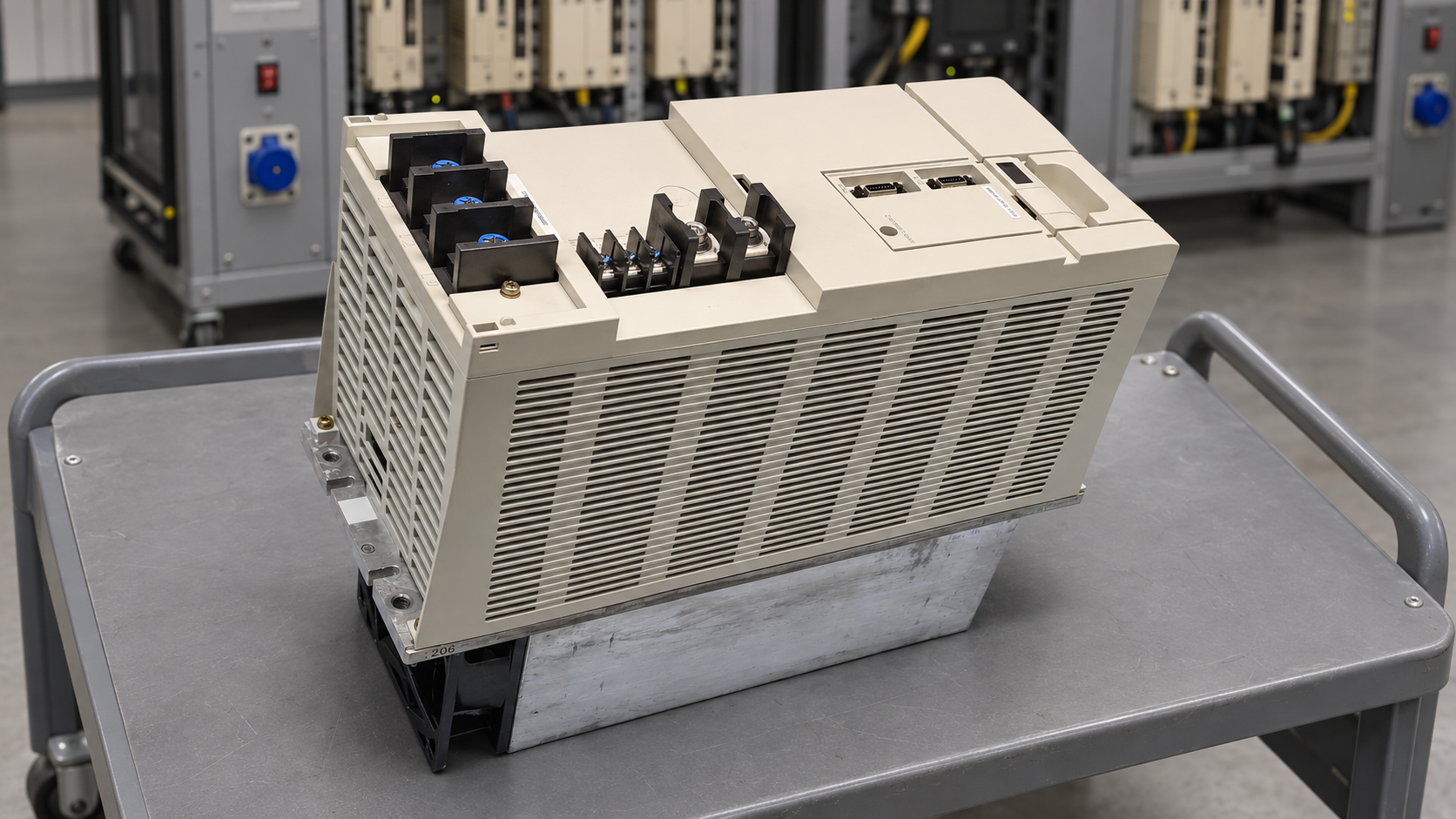 After overhaul: overall view
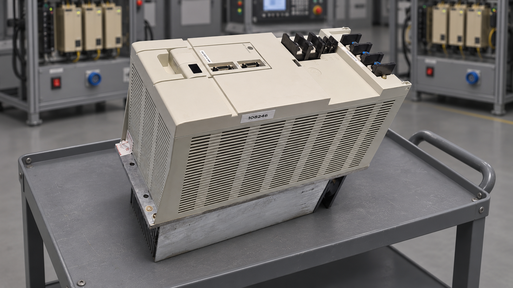 After overhaul: side view
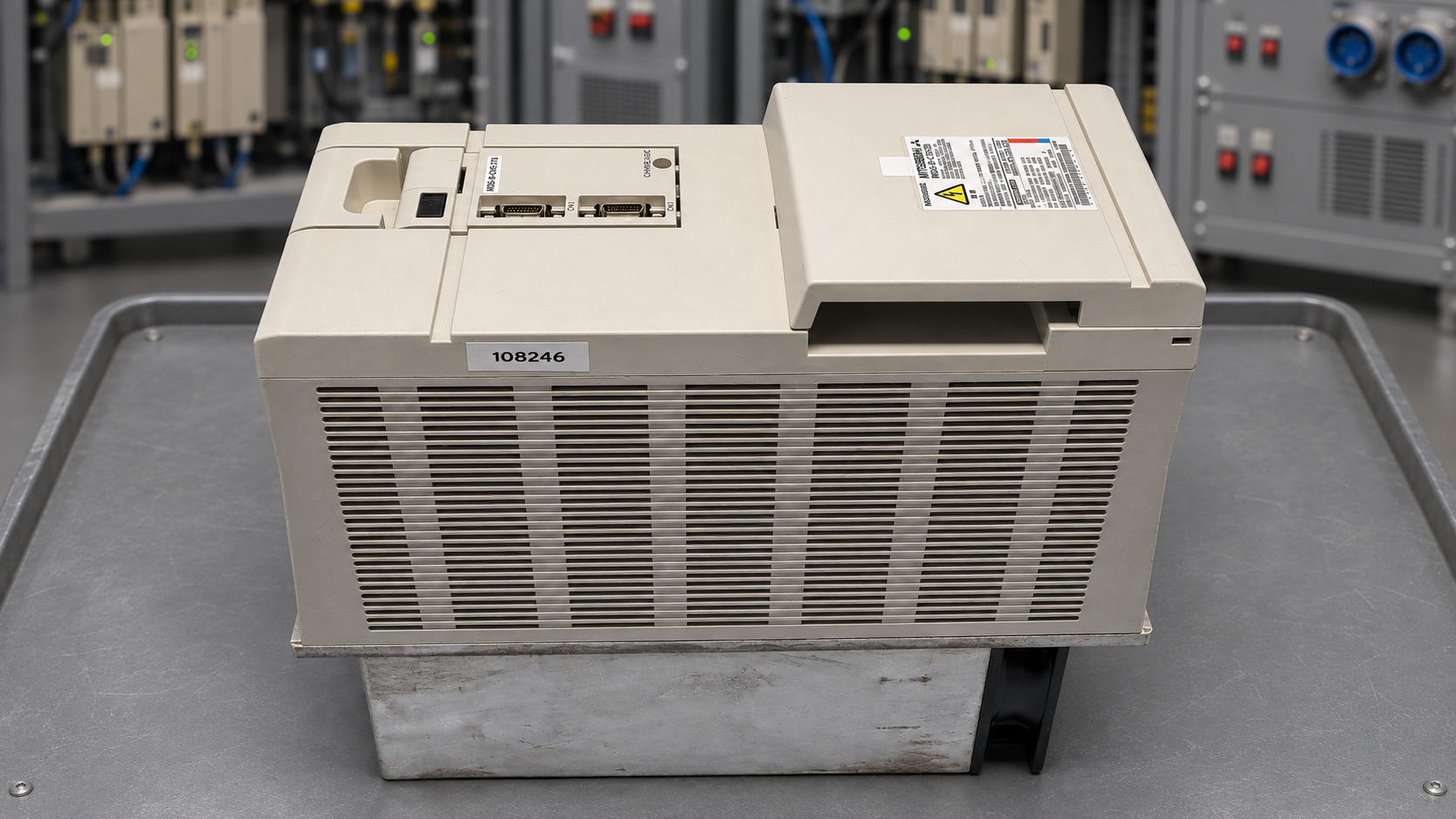 After overhaul: front view
Repair enquiry and matching product
Would you like a Mitsubishi MDS-B-CVE-370 tested or overhauled? Send the full model designation, photos of the displays and a description of the fault. Please confirm availability and the service scope for your particular case.
Matching product in our shop: Mitsubishi MDS-B-CVE-370 Power Supply Unit – view product
General alarm list: MDS-B-CV power supply family
Manufacturer mapping, II-3: alarm number at the connected drive on the left; power supply LED indication on the right. All entries below are general alarms. None is documented for this repair.
| Alarm / LED | Meaning | Source |
|---|
| 65 / 5 | Inrush relay | II-3 |
| 67 / 7 | Phase loss | II-3 |
| 68 / 8 | Watchdog | II-3 |
| 69 / 9 | Ground fault | II-3 |
| 6A / A | Contactor welded | II-3 |
| 6B / b | Inrush relay welded | II-3 |
| 6C / c | Main circuit | II-3 |
| 6E / E | Memory fault | II-3 |
| 75 / L | Overvoltage | II-3 |
| 77 / n | Power module overheating | II-3 |
Maintenance troubleshooting
| Observation | Practical checks |
|---|
| Alarm 77 / n | Inspect fan, cooling surfaces and cabinet ventilation. Manufacturer: II-16. |
| Fault occurs only on the machine | Record operating conditions, CNC message and power supply display; compare these with workshop test conditions. |
| No clear message | Take photos before resetting. Record all involved module models and previous changes. |
| Unit operates but is heavily contaminated | Assess maintenance condition separately; do not judge airflow and fan condition solely by a power-up test. |
| Fault after reinstallation | Have wiring and settings checked against the original documentation. Avoid trial-and-error parameter changes. |
An alarm identifies a monitored condition, not automatically a failed component. Repeated resets without diagnosing the cause are not a repair. Detailed checks must follow the manufacturer documentation applicable to the specific unit and machine.