28.10.2026 by Viktor Siebert
FANUC A06B-6044-H023 AC Spindle Unit: Alarm 12 and overhaul
FANUC A06B-6044-H023 after two years of machine downtime
This FANUC A06B-6044-H023 spindle controller arrived at industrypart with a long history of faults. The customer reported recurring problems when starting the spindle. After two years of machine downtime, another attempt to start it again produced alarms. At our test bench the unit immediately displayed alarm 12. We identified defective transistor modules, power capacitors and control circuitry on the A20B-0009-0534 control board.
Unit data and variant matching
| Item | Documented information |
|---|
| Manufacturer and unit type | FANUC AC Spindle Servo Unit |
| Full designation | A06B-6044-H023 |
| Manufacturer manual classification | MODEL 15, analogue spindle servo series |
| Control board | A20B-0009-0534 |
| Serial number on the pictured nameplate | 2633 |
| Drive function | Control of an AC spindle motor |
| Power assemblies | Transistor modules and DC link with power capacitors |
| Cooling | Fans and heat sinks |
| Documented final test | Motor operation at different speeds |
The MODEL 15 and A20B-0009-0534 classification comes from table 1.1(a) in FANUC maintenance manual B-53425E/09. We do not derive an electrical power rating from the model number. The photographed nameplate does not provide complete voltage, current or power ratings. Replacement requires matching the full unit designation, board variant, ROM version and unit specific settings. A visually similar circuit board does not establish compatibility.
Function, power flow and signal processing
The spindle unit converts incoming electrical energy through a DC link and a transistor power stage into the AC spindle motor supply. Power capacitors smooth and support the DC link. The power stage requires appropriate control signals so that its semiconductors switch in the intended sequence. The control electronics process commands and feedback and monitor operation. The manufacturer manual describes this as an analogue spindle servo series; command processing, feedback and power stage control perform different tasks.
At spindle startup, supply, enable signals, control circuitry and motor must work together. A control circuit fault can therefore matter just as much as a defective power module. Conversely, a short circuit in the motor or output cable can trigger protection in the spindle unit. The displayed alarm must be assessed alongside the electrical findings.
Assemblies and confirmed workshop findings
| Assembly | Function | Finding and action |
|---|
| Transistor modules | Switching motor power | Defective, replaced |
| Power capacitors | Smoothing and supporting the DC link | Defective, replaced |
| A20B-0009-0534 | Control and power stage drive signals | Damaged drive circuitry; individual channels inactive; board repaired |
| Fans | Heat removal | Replaced during overhaul |
Customer reports and incoming test results
Back in 2022 the customer reported the machine messages “20 NMI Not Aus” and “204 Spindle Controller Fehler” when starting the spindle. Worn capacitors were suspected at that time, but this was not confirmed. Repair prospects were considered uncertain because of the age of the series. According to the customer, the machine subsequently continued operating with recurring failures before remaining idle for about two years.
Our incoming test immediately produced alarm 12 on the spindle unit. The earlier machine messages 20 and 204 are therefore not treated as FANUC unit alarms with an equivalent meaning. Their precise origin cannot be determined from the spindle unit alarm table without the relevant machine control documentation. The current findings confirm defective capacitors in the examined unit, but do not retrospectively prove the cause of the 2022 messages.
Alarm 12: excessive DC link current
For the applicable analogue series FANUC defines alarm 12 as “DC link current is excessive”. The diagnostic section lists a short circuit at the output terminals or inside the motor, a defective transistor module and a defective printed circuit board as possible causes. These are alternative diagnostic paths, not faults that necessarily occur together. In this case, defective transistor modules, power capacitors and damaged control circuitry were confirmed.
In comparable cases, distinguish the output cable and motor from the internal power stage. Control signals and the control board supply also belong in the analysis. Replacing only the power modules would not remove a remaining control signal fault. The protective alarm alone neither diagnoses motor damage nor identifies one component to replace. Repairing the control board was an essential part of this repair.
Alarm reference for the analogue FANUC spindle servo series
This overview refers to the MODEL 3 to 40 alarm table in the cited maintenance manual. It is a manufacturer reference, not a list of alarms observed during this repair. The diagnostic approaches are general guidance. The unit version and complete indication must match the table.
| Alarm | Manufacturer description | Meaning | General diagnostic approach |
|---|
| 1 | Motor is overheated | Motor overheating | Examine motor loading and cooling. |
| 2 | Speed deviates excessively | Excessive speed deviation | Distinguish command, feedback, load and power delivery. |
| 3 | DC link fuse F7 is blown | DC link fuse F7 blown | Identify the power circuit fault before replacing the fuse. |
| 4 | Input fuse F1, F2, F3 is blown | Input fuse blown | Distinguish supply faults from internal power circuit faults. |
| 5 | Power supply fuse AF2, AF3 is blown | Board power supply fuse blown | Examine the control supply and connected circuits. |
| 6 | Overspeed (analog) | Analogue overspeed detection | Examine speed feedback and control. |
| 7 | Overspeed (digital) | Digital overspeed detection | Check feedback and processing. |
| 8 | +24 V power voltage is high | 24 V supply too high | Check the internal supply and monitoring. |
| 9 | Radiator is overheated | Heat sink overheating | Consider fans, air passages and loading. |
| 10 | +15 V power voltage is low | 15 V supply too low | Isolate supply faults and possible overload. |
| 11 | DC link voltage is high | DC link voltage too high | Record supply conditions and operating state at the trip. |
| 12 | DC link current is excessive | Excessive DC link current | Distinguish output short circuits, motor, transistor modules and board. |
| 13 | CPU / peripheral circuit defective | CPU or peripheral circuit fault | Examine control electronics and their supply. |
| 14 | ROM defective | ROM fault | Consider memory and the correct unit version. |
| 15 | Optional circuit trouble | Optional circuit fault | Isolate the installed option and its connections. |
Extensive repair and preventive overhaul
We replaced the defective transistor modules and power capacitors, as well as the fans. The A20B-0009-0534 control board was repaired and worn components were renewed. Damage in the power section and its control circuitry was therefore addressed together. With an older assembly this matters because replacing one failed component does not improve the condition of the remaining circuits.
Motor test at different speeds
After the overhaul, the spindle unit was tested with a motor at different speeds. The video documents this test run. No specific speed, test duration or defined load is stated. The footage complements the repair report and shows the unit operating at the test bench.
Maintenance and restarting after prolonged downtime
Clear cooling passages and functioning fans support heat removal. Unusual fan noise, recurring shutdowns and changed startup behaviour should be investigated early. After prolonged downtime, the supply, connections, motor cable and drive electronics deserve a combined assessment. Repeatedly switching on with an unchanged alarm does not replace fault analysis. With aged capacitors, electrical condition provides more useful evidence than appearance alone.
Manufacturer documentation
FANUC AC Spindle Servo Unit Maintenance Manual B-53425E/09: Table 1.1(a), printed page 5 (PDF 9): unit and board classification. Block diagram on page 4 (PDF 8). Alarm table on page 13 (PDF 17); alarm 12 diagnosis on page 23 (PDF 27). Case details additionally come from the workshop report and supplied photographs.
Test bench video
Photos before and after repair
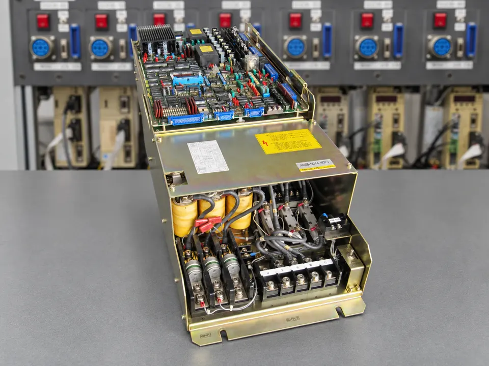 After repair: overall view
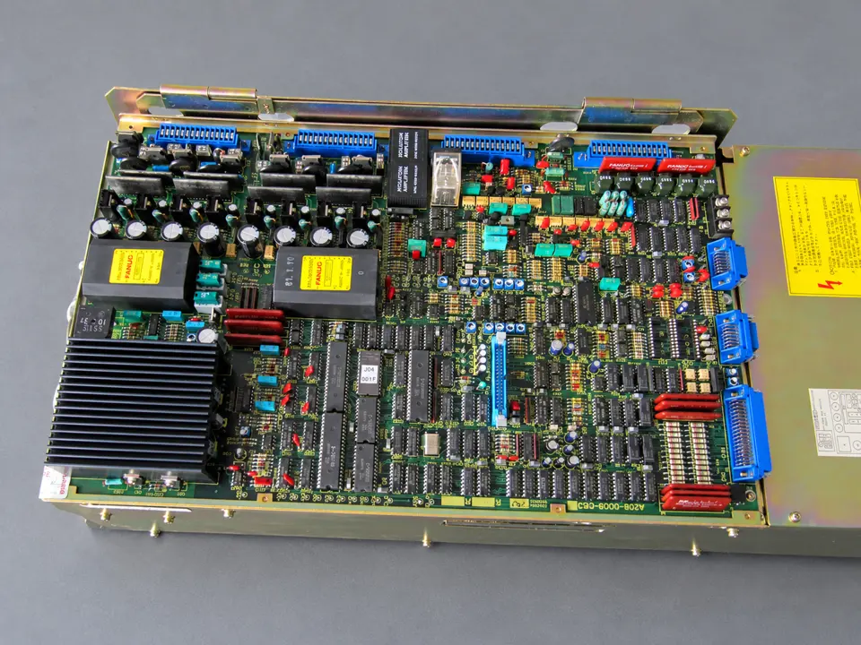 After repair: control board
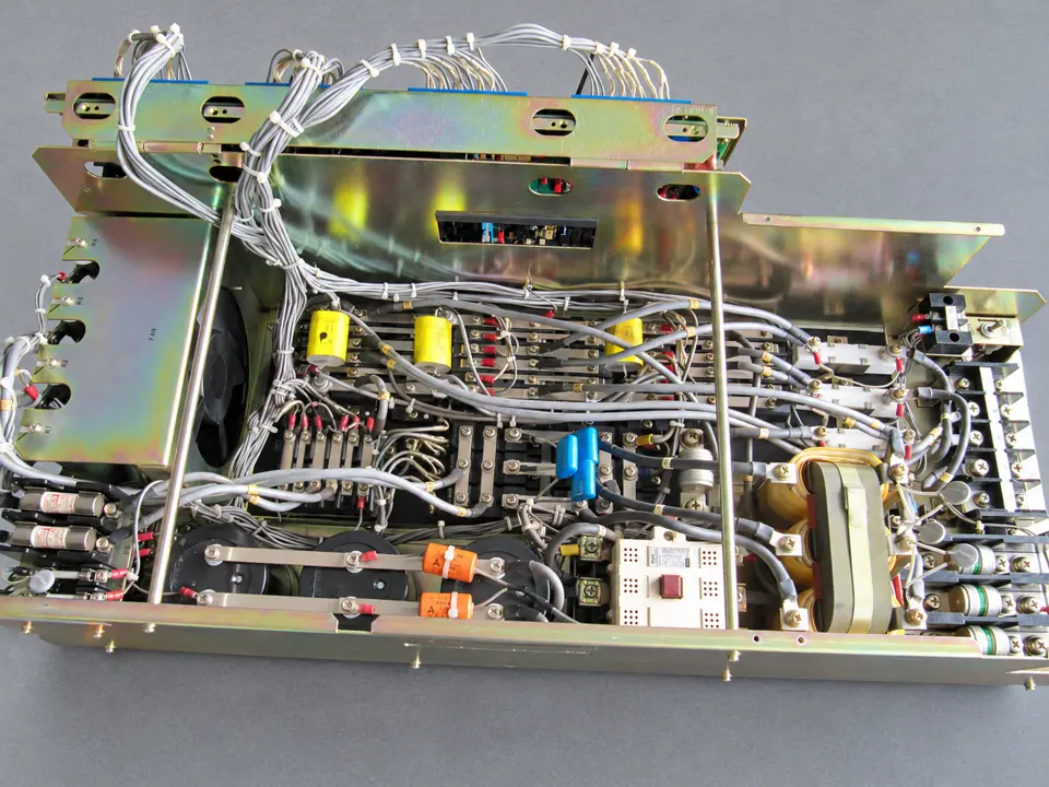 After repair: power section
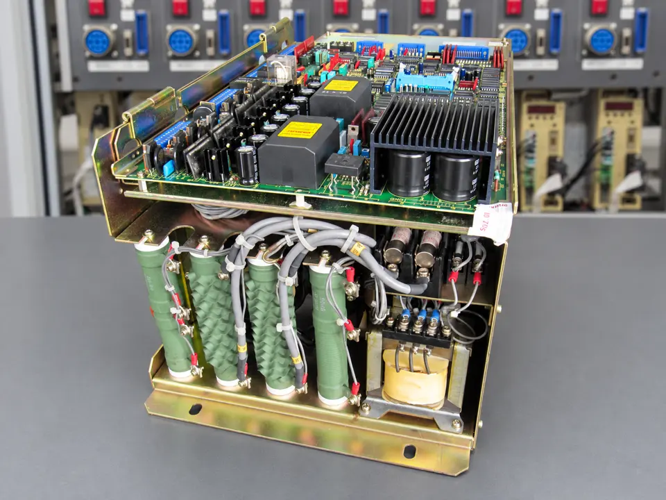 After repair: rear view
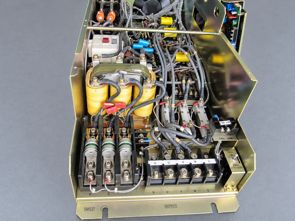 After repair: interior
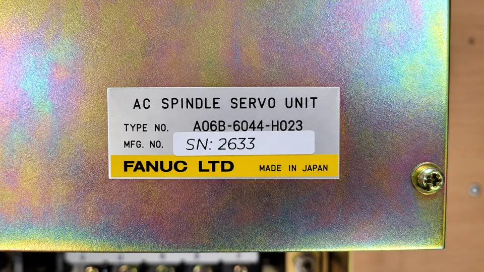 Nameplate: A06B-6044-H023
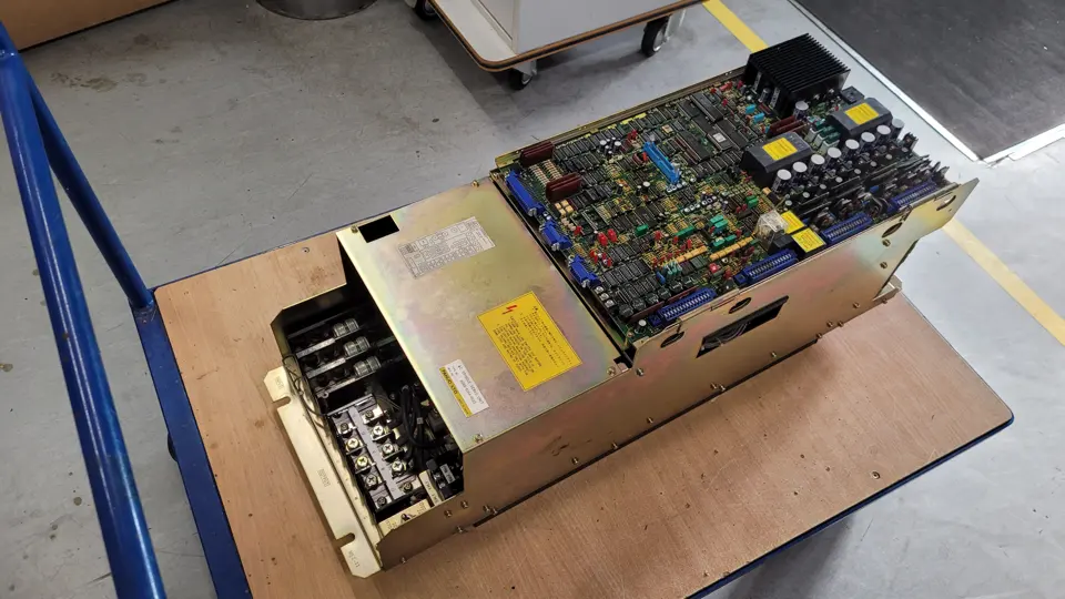 Before repair: overall view
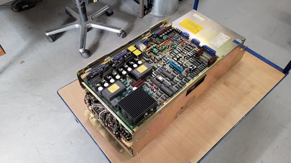 Before repair: side view
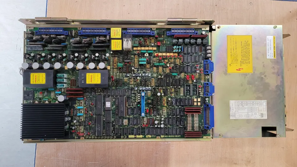 Before repair: control board
Service for FANUC drive electronics
industrypart supports you with diagnostics, repair and preventive overhaul of industrial drive electronics. For more information on repairs, exchange and available equipment, visit our FANUC manufacturer page.