23.10.2025 by Viktor Siebert
Repair of Yaskawa VS-656 MR5 CIMR-MR5N4037Converter and VS-626M5 Inverter CIMR-M5A40370-XXXX
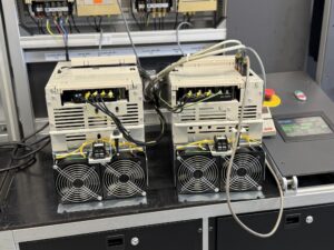
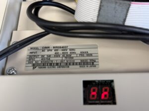
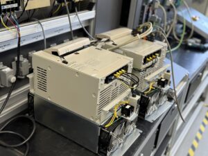
The incoming set consisted of a Yaskawa Converter VS-656 MR5 (CIMR-MR5N4037) and a Yaskawa Inverter VS-626M5 (CIMR-M5A40370-XXXX).
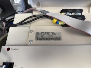
When received, the inverter showed no signs of life, only the CHARGE LED was active, indicating partial DC bus voltage but no control activity.
After disassembly and cleaning, the converter was tested. It started up normally but repeatedly failed under higher load, particularly during regenerative operation. This indicated unstable DC bus regulation and possible load feedback issues.
The inverter remained inactive during all initial tests. Detailed diagnostics revealed that the control section did not initiate the run sequence. In multiple test phases, the DC link, power module, gate drive signals, and internal logic were examined. Some critical components within the power and control circuits were found to be outside tolerance.
The repair process was carried out in several stages:
- Insulation and continuity testing
→ Verification that no low-resistance faults existed between DC bus or output terminals.
- Dynamic DC bus monitoring under load
→ Voltage stability and regeneration behavior observed under various test conditions.
- Replacement of critical control and protection components
→ Restored proper switching control and DC regulation.
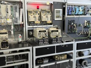
- Functional testing on original test bench
→ Both units tested together with simulated load, ensuring synchronized operation.
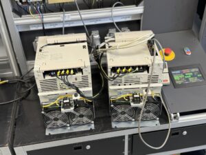
- Extended runtime and thermal verification
→ Six-hour continuous operation with thermal monitoring and regenerative cycles.
After completing the repair, both units operated flawlessly.
Regeneration worked correctly, power transfer remained stable even under varying loads, and all temperature readings stayed within limits.
Preventive Maintenance Recommendations
- Clean cooling fans and air ducts regularly
- Inspect DC link capacitors every 5–7 years
- Keep ambient temperature below 40 °C
- Tighten all terminal screws and check insulation values
- Avoid unbalanced loads on the DC bus
Conclusion
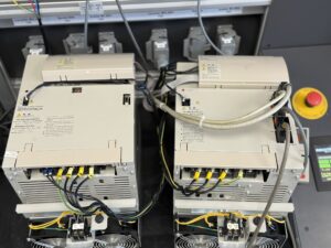
After full reconditioning, both the converter and inverter were restored to original operating condition.
Through detailed diagnostics, preventive replacement of critical elements, and thorough testing, the system now operates stably and reliably again.
This repair significantly extended the service life and improved system reliability for future operation.
Further information such as price and delivery time for:
Yaskawa VS-656 MR5 CIMR-MR5N4037 Converter
Yaskawa VS-656 M5 CIMR-M5A40370-XXXX Inverter
More details about our Yaskawa repair expertise can be found here: Yaskawa Reparatur bei Industrypart
📞 Please feel free to contact us if you have any questions regarding your Omron drive technology. Our experienced team is always available to assist you.
Technical Specifications
| Unit | Model | Input Power | Output | Power | Weight | Origin |
|---|
| Converter | CIMR-MR5N4037 | AC 3PH 400–440 V (50 Hz) / 400–460 V (60 Hz) | DC 540–650 V | 45.8 kW / 60 kVA | 30 kg | Japan |
| Inverter | CIMR-M5A40370-XXXX | DC 540–650 V | AC 3PH 400–460 V | 45.8 kW / 43.6 kVA | 25 kg | Japan |
Typical Alarms and Fault Causes – Converter
| Code | Description | Cause | Corrective Action |
|---|
| 01 | Overcurrent | Output current exceeded detection level | Check wiring, input supply voltage |
| 04 | Main Circuit Fuse Blown | Main fuse blown | Check for short circuits, damaged power section |
| 05 | Overload | Output current exceeded load capacity | Check and reduce load |
| 11 | Output Overvoltage | DC voltage too high | Check power supply and regenerative circuit |
| 12 | Main Circuit Undervoltage | DC bus voltage too low | Check input voltage |
| 13 | Control Circuit Undervoltage | Control supply voltage too low | Verify control supply |
| 14 | Servo Unit Power Fault | Abnormal voltage to servo unit | Check control circuit |
| 16 | Initial Charging Fault | DC bus capacitors not charged | Inspect or replace unit |
| 17 | Power Supply Open Phase | Phase missing on input | Check wiring and input supply |
| 43–44 | Heatsink Overheat 1/2 | Heatsink temperature exceeded limit | Check fan, cooling, ambient temperature |
| D2–F5 | CPU / ROM / EEPROM Fault | Control PCB failure | Replace control PCB |
Typical Alarms and Fault Causes – Inverter
| Code | Description | Details | Corrective Action |
|---|
| AL-01 | Overcurrent | Overcurrent or short circuit at output | Check wiring, motor, and load |
| AL-02 | Ground Fault | Excessive ground current detected | Check insulation between inverter and motor |
| AL-04 | Main Circuit Fuse Blown | DC circuit fuse blown | Check power devices and output wiring |
| AL-10 | Converter Fault | Fault detected in converter unit | Check converter LED status |
| AL-12 | Main Circuit Undervoltage | DC bus voltage too low | Verify input voltage |
| AL-30 | Encoder Cable Disconnection | Encoder signal lost | Inspect encoder wiring |
| AL-40–44 | Motor/Heatsink Overheat | Temperature exceeded limit | Check fans, cooling, and surroundings |
| AL-D2–AL-F2 | CPU/EEPROM/ROM Error | Electronic control fault | Replace control PCB |
Functional Description
The VS-656 MR5 Converter provides a stable DC bus voltage for the connected VS-626M5 Inverter, which controls the AC motor.
This combination is designed for high-performance drive systems in the 45–50 kW range.
The converter manages power regeneration during deceleration, while the inverter controls torque and speed with precision feedback.
Operating Environment
These units are typically used in CNC machines (e.g., Mazak, Mori Seiki, YCM) where high precision and reliability are essential.
They serve as spindle or feed drives, often in high-speed machining environments with regenerative energy return to the power grid.