22.11.2025 by Viktor Siebert
Repair of a Yaskawa CIMR-MRXN2011 Converter with Recurring Failure After Factory Repair
Initial Situation at the Customer Site
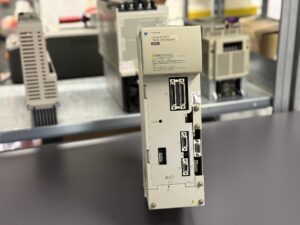
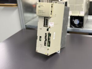
The Yaskawa CIMR-MRXN2011 converter from a STAR Micronics CNC machine was sent to us after the operator experienced increasingly unstable machine startups. The machine showed a very specific pattern: on the first power-up, the converter almost always triggered a Profibus communication error, preventing the CNC from entering its ready state. On the second attempt, the machine usually started normally. This behaviour persisted for months and worsened over time, especially after cold starts.
The device had been repaired by Yaskawa approximately one year earlier. At that time the internal power supply section had been repaired and refurbished. Only a few months later a new failure pattern emerged, seemingly unrelated to the previous repair. The customer suspected a communication issue or a thermal fault but could not determine the root cause.
Diagnosis on Our STAR Test Machine
Because we operate a fully equipped STAR test machine, we were able to reproduce the customer’s issue under realistic conditions. The very first cold start resulted in the same Profibus alarm. A second attempt worked flawlessly. This behaviour repeated itself under various conditions, particularly at low ambient temperatures or after long idle periods.
This strongly suggested a temperature-sensitive electronics problem rather than a mechanical or wiring-related issue.
Internal Condition Analysis
Upon disassembling the device, we found that the internal power supply – previously repaired by Yaskawa – was indeed in very good condition. Many components had been replaced or reworked professionally. However, the remainder of the converter had not been touched.
This included all DC-link capacitors, logic circuits and especially the Profibus communication board JUSP-ACPCCLB-N5-V.
Several DC-link capacitors showed clear signs of aging, such as drying and increased ESR. In high-duty CNC environments this significantly increases the risk of unstable DC bus voltage.
More serious, however, was the condition of the communication board. Several SMD electrolytic capacitors showed early leakage. The subtle electrolyte residues had increased ESR and altered the signal behaviour of the communication interface. Profibus is extremely sensitive to such changes, and millivolt-level variations can cause the entire communication chain to collapse.
Technical Root Cause and Evaluation
Oscilloscope measurements, bus analysis and temperature profiling clearly revealed the behaviour: the Profibus board operated outside its normal tolerance window when cold. After a few seconds of operation, slight warming stabilised the capacitance values and the board fell back into normal operation.
This failure behaviour is very typical for aging SMD capacitors. It is also a common outcome of partial repairs, where the manufacturer repairs only the directly affected subsystem, leaving other aged components unchanged.
Repair Measures Executed
We performed a full preventive overhaul according to the Industrypart standard:
- Replacement of all DC-link capacitors
- Renewal of all SMD electrolytic capacitors on the Profibus board
- Reworking all solder joints in high-stress areas
- Cleaning and neutralising electrolyte residues
- Verification of the previously repaired power supply
- Full functional and load testing on our STAR test machine
We executed over 60 start-stop cycles, temperature variations and load simulations. The converter passed all tests without a single communication error.
Result and Customer Benefit
The customer received a fully refurbished device, not only repaired for the immediate fault but also restored to a long-term stable condition. By replacing all critical aging components, the risk of further failures was greatly reduced. Unlike a minimal repair approach, this solution ensures long-term operational reliability.
Preventive Recommendations
We advise customers to follow these guidelines:
- Replace DC-link capacitors every 7 to 10 years
- Periodically inspect communication boards
- Keep machine ventilation clean
- Monitor supply voltage quality
Conclusion
This case demonstrates that even after a factory repair a device can develop new weaknesses if only part of the electronics is refurbished. Through a comprehensive preventive overhaul these risks can be eliminated. The repair of the CIMR-MRXN2011 clearly shows how essential holistic diagnostics and experience with STAR Micronics environments are to avoid recurring machine failures.
Further information such as price and delivery time for:
Yaskawa CIMR-MRXN2011 Converter
More details about our Yaskawa repair expertise can be found here: Yaskawa Reparatur bei Industrypart
📞 Please feel free to contact us if you have any questions regarding your Omron drive technology. Our experienced team is always available to assist you.
Device Data
| Parameter | Value |
|---|
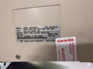
| Model | CIMR-MRXN2011 |
| Input | AC3PH 200–220 V 50 Hz / 200–230 V 60 Hz |
| Rated current | Cont. 31 A, 50 % ED 46 A |
| Output | DC270–325 V, Cont. 39 A, 50 % ED 58 A |
| Mass | 5.3 kg |
| Control | Profibus interface via JUSP-ACPCCLB-N5-V |
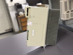
| Cooling | Forced ventilation, internal heatsink |
| Manufacturer | Yaskawa Electric |
| Application | CNC machines, especially STAR Micronics |
| Manual reference | MR5/M5 Converter Fault Tables |
Application Environment & Compatible Devices
The CIMR-MRXN2011 is installed in STAR Micronics Swiss-type machines, where it forms the central DC-link converter.
It communicates through Profibus with the CNC controller and operates together with:
- Yaskawa Servopacks (SGDM, SGDH, Sigma-II/III)
- STAR axis control modules
- JUSP-ACPCCLB-N5-V communication boards
Typical environment:
High temperature, vibration, fluctuating line voltage, 24/7 operation.
Functional Description
The converter performs the following tasks:
- Rectification of the mains voltage and generation of a stabilised DC link (approx. 270–325 V)
- Brake chopper control, overcurrent detection, overtemperature protection
- Communication with CNC via Profibus
- Supplying Servopacks via the shared DC bus
- Protective functions such as Overcurrent, Overvoltage, Undervoltage based on MR5 manual tables
The Profibus card JUSP-ACPCCLB-N5-V is responsible for all fieldbus communication.
Alarms & Troubleshooting
| Code | Description | Cause | Solution |
|---|
| OC | Overcurrent | Overload, defective transistor stage | Check power stage, replace IGBTs |
| UV | Undervoltage | Unstable input | Check mains supply |
| OV | Overvoltage | Regeneration or line spikes | Check DC link capacitors |
| OH | Overheat | Heatsink > 85 °C | Clean fan and heatsink |
| PF | Power Frequency Error | Line frequency deviation | Stabilise input |
| MC | Main Contactor Fault | Contactor not functioning | Check contacts and driver |
| CPF | Control PCB Error | Low-voltage section defective | Check 5V/12V regulators |
| COMM | Bus error on startup | Faulty Profibus board | Replace communication card |
Components
| Component | Designation | Function | Inspection notes |
|---|
| Control PCB | JUSP-ACPCALB-V | Main logic | Check 5/12 V |
| Profibus board | JUSP-ACPCCLB-N5-V | Fieldbus | Inspect SMD electrolytics |
| Power PCB | YPHT31291-1B | Rectifier & DC link | Test IGBTs, diodes |
| Power module | MRXN2011 Power Stage | Power path | Isolation & load testing |
| DC link capacitors | 1-PCB / 3-PCB | Voltage smoothing | Measure ESR & capacitance |