04.11.2025 by Viktor Siebert
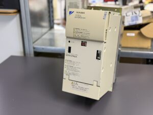
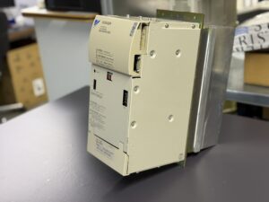
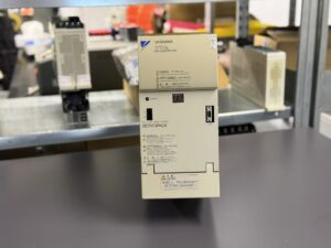
Repair of a Yaskawa CIMR-MR5N2018 Converter Unit
Fault Description and Diagnosis
At the customer’s facility, the converter suddenly stopped working and displayed Fault “01”, corresponding to Overcurrent, as described in Yaskawa’s documentation. In practice, this alarm can have various root causes: temporary load surges, wiring anomalies, component aging, or protective circuit activation triggered by internal imbalance.
Upon arrival in our workshop, the converter was completely non-functional. Initial inspection showed traces of heat accumulation and reduced airflow due to partial obstruction of the ventilation path. This suggested a thermal influence as a possible trigger.
The diagnostic process began with isolation testing, followed by a detailed current behavior analysis under simulated load. The measurement results indicated irregularities in current distribution, typical for converters under stress or near end-of-life of certain components.
The unit was disassembled entirely. Each circuit board especially the control board (YPHT31149-xD) and power board (YPCT31244-1B / ETC626095) was carefully examined for thermal wear, degraded solder joints, and irregularities in gate-drive behavior. The investigation revealed that the failure was not a single hardware fault but the result of aging processes, heat-related drift, and early instability within the power drive section.
Repair Process
After diagnosis, the converter underwent a complete overhaul. All temperature-stressed components were checked and replaced where necessary. Electrolytic capacitors, connectors, and control interface sections were renewed to ensure consistent operation.
The control board was tested step-by-step: from logic input through signal amplification to PWM generation. On our test bench, the unit was paired with an MR5 servo amplifier and subjected to various load and temperature cycles. The converter successfully maintained stable DC output during transient tests and responded correctly to regenerative braking conditions.
Thermal endurance testing followed, confirming that the DC link voltage remained within nominal limits and that the heat-sink control circuit operated precisely as per factory specifications.
Preventive Maintenance and Quality Assurance
For converter units of this class, we recommend preventive replacement of high-stress components — particularly electrolytic capacitors and cooling fans every 8 to 10 years. Regular cleaning of control boards and airflow paths is equally essential since even minor dust or oil contamination can reduce cooling efficiency.
The repaired unit, passed all functional and safety tests. Quality verification included isolation resistance measurement, DC-bus stability monitoring, start-up simulation, and dynamic load cycling. After final inspection, the unit was sealed, labeled, and released for reintegration into the machine.
Conclusion
This case clearly demonstrates that Fault 01 (Overcurrent) rarely indicates a simple component failure. Instead, it often results from complex interaction between electrical stress, temperature, and component aging. Through systematic analysis, thorough cleaning, and preventive refurbishment, we were able to restore the Yaskawa CIMR-MR5N2018 to full working condition.
Experience shows that proactive maintenance on MR5-series converters not only prevents costly downtime but significantly extends the service life of the entire CNC drive system. Such detailed overhauls reinforce long-term reliability a principle we continue to uphold for every Yaskawa converter we repair.
Further information such as price and delivery time for:
Yaskawa CIMR-MR5N2018 Converter Unit
More details about our Yaskawa repair expertise can be found here: Yaskawa Reparatur bei Industrypart
📞 Please feel free to contact us if you have any questions regarding your Omron drive technology. Our experienced team is always available to assist you.
Technical Specifications
| Specification | Value | Remark |
|---|
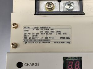
| Manufacturer | Yaskawa Electric Corporation | Made in Japan |
| Model | CIMR-MR5N2018 | Converter Unit |
| Series | MR5 | Varispeed-626MR5 Series |
| Input Voltage (AC) | 3-Phase 200–230 V AC (50/60 Hz) | Main power input |
| Input Capacity | 30 kVA | Rated load |
| Output Voltage (DC) | 270–325 V DC | DC link voltage |
| Output Power | 22.9 kW | Power for servo/spindle amplifiers |
| Specification Code | 20185E | Model identification |
| Program Version | 0021 | Control firmware |
| Weight | Approx. 12 kg | Standard unit |
| Control PCB | 1PCB – YPHT31149-xD | Logic and signal section |
| Power PCB | 2PCB – YPCT31244-1B / ETC626095 | Power module control |
| Power Module | Integrated IGBT block | Main switching stage |
Overview
The Yaskawa CIMR-MR5N2018 converter unit is part of the Varispeed-626MR5 family, designed to provide DC power for servo and spindle drives in precision machine tools. It converts the incoming three-phase AC voltage into a regulated DC bus, ensuring reliable and stable energy supply for demanding CNC operations.
With a rated output of 22.9 kW and an input capacity of 30 kVA, this converter belongs to the high-power segment of the MR5 series. Reliability, however, depends strongly on proper cooling and periodic preventive maintenance.
Alarm and Fault Table – CIMR-MR5N2018 Converter
| Fault No. | Name (EN) | Meaning (EN) | Corrective Action (EN) |
|---|
| 01 | Overcurrent | Output current exceeded detection level. | Check wiring, input voltage, and load. |
| 04 | Main fuse blown | Main circuit fuse damaged. | Inspect for short circuit or transistor failure. |
| 05 | Overload | Output exceeded rated current. | Reduce load, check servo. |
| 11 | Output overvoltage | DC output exceeded limit. | Verify input voltage. |
| 12 | Main circuit undervoltage | DC bus below threshold. | Check power input. |
| 13 | Control undervoltage | Control supply too low. | Verify control voltage. |
| 14 | Servo supply fault | Servo voltage unstable. | Check servo supply. |
| 15 | Frequency fault | Power frequency deviation > ±5 %. | Check line frequency. |
| 16 | Initial charge fault | Capacitor not charged. | Replace the unit. |
| 17 | Open phase | Missing input phase. | Inspect wiring. |
| 23 | Contactor fault | Magnetic contactor failed. | Replace the unit. |
| 43–47 | Overtemperature / PCB fault | Cooling or temperature circuit abnormal. | Check environment and cooling. |