10.12.2025 by Viktor Siebert
Repair of a Yaskawa CACR-SR03SB1BFY199 AC Servopack with immediate alarm 1 overcurrent
When the Servopack CACR SR03SB1BFY199 arrived at our workshop the customer’s description was short and to the point. After a weekend shutdown the machine would not start again, as soon as the control was powered up a fault appeared at the servo drive. The internal seven segment display immediately showed alarm 1, even before the motor had any chance to move. The customer had already checked main switch and fuses, the mains supply looked fine.
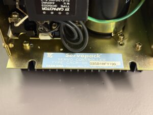
As always we started with proper documentation. Nameplate and Y199 marking were photographed and the customer data recorded in our system. Since this is an OEM special version it was clear that the control board and its parameter set should be preserved. Replacing the unit by a standard SR03BB might work electrically but would require significant parameter work and wiring changes on the machine.
After the initial visual inspection we carried out the electrical pre check. Motor and cables were measured with an insulation tester to exclude an external short circuit. The insulation values were good so the overcurrent condition had to be caused inside the unit. Alarm 1 without any motor rotation is usually a sign of a hard short in the power stage such as a blown transistor module or a burned copper trace in the main current path.
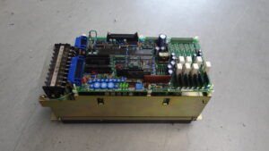
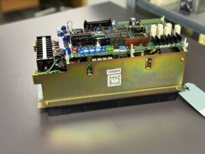
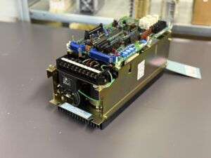
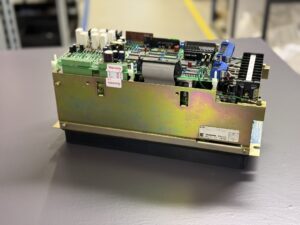
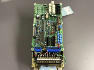
The Servopack was opened and inspected in detail. At the front edge of the heatsink we noticed dark discolorations. One connection lead between the transistor block and the shunt had changed colour, the solder joint next to it was dull and showed typical signs of thermal overload. On the solder side of the PCB several hairline cracks were visible around the shunt solder pads. In the DC bus area dust and coolant residue had accumulated over the years which further increased thermal stress.
The next step was an electrical test of the power stage. Measurements between motor terminals and DC bus revealed an almost zero ohm connection on one phase. That leg of the transistor bridge was clearly shorted. Such a defect explains perfectly why the overcurrent protection reacts at power up. As soon as the DC bus is charged a large current flows through the shorted transistor, the shunt detects it and the drive trips immediately.
The repair therefore included replacement of the whole power module of that size. The transistor block was removed from the heatsink, the contact surface cleaned and prepared with fresh thermal compound. At the same time all shunt resistors were desoldered, measured and replaced by suitable types. Even if only one branch showed visible damage we always replace the complete shunt set in such cases, as they were thermally stressed together.
When a transistor fails that hard there is also a high risk that the driver stage and parts of the gate circuitry are affected. For this reason the control board was thoroughly checked in this section as well. Driver transistors and associated resistors were tested and two components showed suspicious values and were replaced as a precaution. At the same time we examined the A D frontend of the current measurement since the manual correctly points out that an A D error or shifted offset can also lead to misinterpretation of currents.
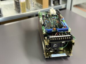
During the repair we also checked the DC bus capacitors for capacity and ESR. The unit had already spent many years in industrial operation. The values were still within specification but with little reserve for future service. Since the capacitors had to be desoldered anyway we decided to replace them as a preventive measure. This reduces stress on the power devices during load changes and stabilises the DC bus voltage.
After completing the solder work the board was thoroughly cleaned. Old flux residues and dust were removed to avoid leakage paths. Then the Servopack was re assembled and powered up step by step on our test bench. First only the control supply was applied, the fault memory checked and the internal voltages plus minus 12 V and plus 5 V measured. Afterwards the main DC bus was ramped up via an isolating transformer with current limit. At that stage it was crucial that no overcurrent occurred any more and the display returned to normal state.
In the next step the original matching 0.3 kW Yaskawa servo motor was connected. Initially without load the whole speed range was driven with an analog reference of plus minus 6 V. The current stayed in a healthy region and the speed monitor signal matched the factory specification. Then the system was tested under load. For this we use a defined inertia with a brake on the test stand to simulate accelerations and decelerations similar to those in the machine.
Especially important in this repair case was verification of the overcurrent protection itself. The alarm must trigger reliably in the event of a real fault but must not disturb normal operation. By running defined overload tests and current step responses we verified the behaviour of the protection. The drive was operated close to its rated current without nuisance trips but shut down immediately when we forced a real overcurrent condition.
Finally the unit received a complete test report as usual. This includes insulation values, commissioning data, current and temperature plots and photos from before and after the repair. The customer therefore receives not only a working drive but also a condition report and recommendations for preventive action. In this case we recommended regular cabinet cleaning and inspection of the ventilation system because it was obvious that dust and coolant mist had contributed to thermal stress over the years.
With that the CACR SR03SB1BFY199 was ready again for many more operating hours in the machine without alarm 1 stopping production at power up.
Preventive measures for the customer
- Regular cabinet cleaning: Dust and oil mist on heatsinks and PCBs increase temperature and stress power modules and shunts. A visual check and cleaning at least once per year is recommended.
- Monitor ventilation and temperature: Inspect fans, filter mats and airflow in the cabinet so that the maximum ambient temperature of 55 degrees Celsius is not exceeded.
- Check motor and cables: Especially on older machines measure motor insulation and inspect servo cables. A shorted motor can destroy even a freshly repaired Servopack.
- Tighten terminals: Regularly check mains and motor terminals. Loose screws cause local heating and can overload transistors.
- Replace DC bus capacitors preventively: After 10 to 15 years of service a capacitor replacement is advisable to keep DC bus voltage and ripple in a safe range.
- Relieve encoder cables mechanically: Route cables at connector 2CN without tension in order to avoid broken conductors due to vibration.
Conclusion
Alarm 1 overcurrent on a Yaskawa CACR SR03SB1BFY199 is a classic protection mechanism and mostly points to a serious defect in the power stage. If the fault already appears at power up the bridge is usually shorted. With systematic diagnostics, proper semiconductor testing and targeted component replacement the Servopack can be restored to full function.
The combination of electrical repair, mechanical cleaning and preventive replacement of critical parts significantly extends the lifetime of the drive. At the same time unnecessary secondary damage to motors and CNC control is avoided. For the user this means less unplanned downtime and better predictability of maintenance intervals.
To mentioned Yaskawa Drive: Yaskawa CACR-SR03SB1BFY199 AC Servopack
More details about our Yaskawa repair services can be found here:
Yaskawa drive Repair by Industrypart
📞 Feel free to contact us with any questions about your Yaskawa drive technology.
Our expert team is happy to help!
Technical Specifications:
| Parameter | Value / Description |
|---|
| Model | CACR-SR03SB1BFY199 AC Servopack |
| Series | CACR-SR series, Servopack for speed control with analog speed reference |
| Rated power | 0.3 kW servo motor power, approx. 0.4 HP |
| Rated output current | Approx. 3 A RMS for 0.3 kW USAME or USAFE motors |
| Maximum output current | Approx. 7.3 A short time according to Servopack table |
| Main power supply | 3 phase 200 to 230 V AC plus minus 10 percent 50 or 60 Hz |
| Control power supply | 1 phase 200 to 230 V AC 50 or 60 Hz |
| Control method | Transistor PWM servo amplifier, analog speed control with plus minus 6 V reference |
| Feedback | Incremental encoder, typically 6000 pulses per revolution, OEM variant Y199 with customized parameter set |
| Command interface | Analog speed command, separate inputs for servo ON, direction, current limit |
| Protective functions | Overcurrent, overload, overvoltage, undervoltage, regenerative trouble, overheat, open phase, CPU and A D error, dynamic brake |
| Cooling | Convection cooling with large heatsink, cabinet ventilation recommended |
| Mechanical design | Wall mounting, base mounting, terminals at the bottom |
| Weight | Approx. 5.5 kg for SR03BB Servopack size |
| Manual reference | Yaskawa AC Servo Drives M F S D Series Bulletin TSE S800 2.1J, chapter 12 troubleshooting |
| Special suffix Y199 | OEM version with fixed gain settings, adapted signal wiring and partly fixed functions, hardware of power stage largely identical to CACR SR03SB1BF |
Application environment and compatible equipment
The Yaskawa CACR SR03SB1BFY199 is a small AC servo drive for classic machine tools, handling axes and feed drives. Typical applications are:
- Feed axes, turrets or tool magazines in CNC lathes and milling machines
- Feed drives on older Siemens or Yaskawa CNC controls with analog speed reference
- Small positioning axes in transfer lines or special purpose machines
Compatible motors are mainly Yaskawa AC servo motors of the U and F series around 0.3 kW, for example USAFED-03 with 6000 pulse incremental encoders.
The drive is usually installed in a closed control cabinet. Allowed environment:
- Ambient temperature 0 to 55 degrees Celsius
- Relative humidity 20 to 80 percent non condensing
- Free of conductive dust, aggressive gases, heavy vibration and direct spray of oil or coolant
Because of the Y199 suffix the unit is factory tuned for a specific machine builder. The combination of Servopack and motor is therefore fixed in the machine and parameter changes are only possible in a limited way.
Functional description
The CACR-SR03SB1BFY199 is an analog speed controller. The main functional blocks are:
- Mains rectifier and DC bus: Three phase mains voltage is rectified, smoothed in the DC bus and supplied to the transistor bridge.
- Power stage: A transistor PWM bridge feeds the motor with a sinusoidal modulated voltage. Current is measured via shunts and in case of overcurrent the bridge is shut down within microseconds.
- Control loops:
- Speed control loop with analog plus minus 6 V reference for rated speed.
- Current control loop for fast current limiting.
- Protection functions for overcurrent, overload, overvoltage, undervoltage and overtemperature.
Feedback processing: Incremental encoder signals A B Z are fed via connector 2CN. The Servopack derives speed feedback and optionally position information from these signals.
Inputs and outputs:
- Inputs for servo ON, direction, external current limit and overtravel limit switches.
- Outputs for servo ready, alarm, current limit active plus torque and speed monitor outputs.
- Safety functions: In case of a fault the power stage is blocked. A dynamic brake circuit can short the motor phases to decelerate the shaft in emergency conditions.
Due to the Y199 OEM execution some parameters and signal assignments are tailored to the original machine. For repair work it is important to keep these OEM adaptations and not to overwrite them with standard Servopack settings.
Alarm messages and troubleshooting
The seven segment display of the CACR-SR shows internal faults as codes. The following table summarises typical LED indications and corrective actions based on the original manual
| Code LED | Name | Description | Typical cause | Recommended action |
|---|
| 1 | Overcurrent | Output current exceeds limit, instantly at power up or servo ON | Shorted transistor module, defective shunt, shorted motor or cable | Measure insulation of motor and cable, test power module, replace faulty parts |
| 2 | Circuit protector tripped | Line breaker or MCCB has tripped | Short in main circuit, damaged transistor, wrong R S T wiring | Check mains side, test transistors, power up via isolating transformer |
| 3 | Regenerative trouble | Error in regeneration and braking circuit | Defective regeneration transistor, open brake resistor, wiring error | Check regeneration path and resistor, replace damaged components |
| 4 | Overvoltage | DC bus voltage too high, especially during braking | Mains voltage too high, wrong transformer, regeneration not working | Check mains, install transformer if needed, repair regeneration circuit |
| 5 | Overspeed | Motor speed exceeds allowed limit | Wrong encoder signals, wrong tuning, incorrect motor data | Check encoder, verify parameters, retune controller |
| 6 | Voltage drop | DC bus undervoltage | Mains voltage too low, undersized supply cable, supply relay dropping out | Check mains and cable cross section |
| 7 | Overload | Thermal overload of drive, continuous current above rating | Mechanical overload, blocked motor, sticky ballscrew | Check mechanics, measure motor current, remove cause |
| 8 | Heat sink overheat | Heatsink temperature above limit | Poor cabinet ventilation, dust on heatsink | Improve cooling, clean drive |
| 9 | A D error | Error in current A D converter | Defective A D circuitry or shunt, lost offset calibration | Check control board, shunts and A D frontend, replace as needed |
| A | CPU error | Processor fault or software timeout | Defective microcontroller or logic, unstable supply voltages | Replace control board, check regulators and capacitors |
| B | Open phase | Missing phase on mains side | Phase loss, blown fuse, loose terminals | Inspect mains R S T, tighten terminals |
| C | Overrun prevention | Excessive motor run out or wrong motor encoder wiring | Motor phases swapped, wrong encoder wiring, wrong motor type | Check motor connections and encoder mapping, use correct motor type |
Components
| Assembly | Designation / Code | Function |
|---|
| Control board | 1 PWB main board | Control loops, logic, A D converter, encoder interface |
| Power stage | Transistor bridge | Feeds motor from DC bus |
| Shunt resistors | Current shunts in DC path | Current measurement for protection and torque control |
| DC bus capacitors | Electrolytic capacitors | DC smoothing and energy storage |
| Regeneration branch | Regen transistor and resistor | Dissipates braking energy |
| Auxiliary power supply | Low voltage supply | Generates plus minus 12 V and plus 5 V for electronics and encoder |
| Encoder interface | 2CN connector and optocouplers | Processes incremental encoder signals A B Z |
| I O stage | Optocouplers for control I O | Isolation of servo ON, direction, limit switches and alarm outputs |
| Heatsink and mounting | Aluminium heatsink | Dissipates heat from power module |