17.11.2025 by Viktor Siebert
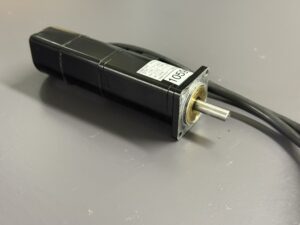
Repair of an Omron AC Servo Motor R7M-A10030-BS1 with encoder failure and full load test on Omron R7D-AP01H Ver.22
Initial Situation and Error Pattern
The Omron AC servo motor R7M-A10030-BS1 was sent in by the customer because the axis had become unreliable during production and repeatedly stopped without warning. The corresponding servo drive R7D-AP01H Ver.22 repeatedly reported encoder errors. At first the faults occurred only sporadically, but within a few days smooth movement was no longer possible. The machine refused to complete the reference move and stopped immediately. These symptoms indicated severely disturbed feedback. Already during the first manual rotation of the shaft it became noticeable that the rotor did not run smoothly. A slight scratching noise inside the unit was audible, which suggested possible bearing damage and therefore a mechanical influence on the encoder.
Diagnostic Phase and Detailed Fault Analysis
The motor was first electrically isolated and checked with an oscilloscope connected to the test inputs of the R7D drive. The A and B channels of the installed Yaskawa TRD-FY2000 encoder showed massive irregularities. The signal amplitude dropped unexpectedly and the spacing between the signal edges varied significantly. This created sporadic A.C3 and A.C2 faults. Additionally, a visible phase shift between A and B was detected, which is a typical sign of an encoder with internal bearing failure. The outer motor housing showed traces of coolant exposure. A visual inspection of the front flange indicated that fine coolant mist had entered the motor over a long period of time. Through the shaft seal area the moisture had reached the bearings and initiated corrosion.
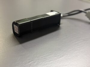
Disassembly and Condition of Internal Components
Once the motor was opened, the full extent of the damage became evident. The bearings were discoloured due to mixed grease and coolant. The front bearing ran roughly and already had axial play. This caused the rotor to run off centre and created additional mechanical stress on the encoder. Moisture had migrated into the encoder chamber. Rust particles and residues were visible around the encoder housing, originating from the deteriorated motor bearing. The bearing inside the encoder was severely worn and blocked intermittently. This caused irregular torque peaks and unstable rotation of the encoder shaft, which resulted in disrupted pulse trains that the drive correctly identified as encoder failures. The encoder circuit board also showed signs of early surface oxidation.
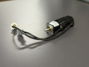
Repair Process and Replacement of Critical Components
The motor was fully disassembled and cleaned. All rotating components were removed. The stator windings were tested with a high voltage insulation tester and showed no electrical damage. All bearings were replaced, including the shaft seal. The damaged TRD-FY2000 encoder was removed completely. A new encoder of the same type was installed and precisely aligned. The centricity was verified using a dial indicator because even minimal misalignment can lead to signal distortion in this motor series. All cable connections were renewed and sealed against moisture. After reassembly, the electrical test demonstrated clean and symmetrical A and B pulse patterns with correct ninety degree phase shift.
Load Test and Quality Verification
For final validation the motor was connected to our servo load test bench. The setup consists of a regulated power supply, an Omron R7D-AP01H Ver.22 drive and an active load module that simulates acceleration profiles. The motor underwent several test cycles. First a no load test confirmed stable encoder pulses. Then dynamic load tests with gradually increasing torque were performed. A thermal endurance test of forty minutes followed. Throughout the entire test sequence the feedback remained perfectly stable. No encoder errors occurred and the drive consistently displayed Ready status. The bearing temperature remained within normal limits. A final documented end test confirmed the overall condition.
Summary of Repair Result
The root cause of the failure was the slow ingress of coolant, which over several months damaged the bearings and eventually destroyed the encoder. By replacing the bearings, renewing the sealing system and installing a new encoder, the motor was restored to its original functional state. The customer receives a fully refurbished motor with documented measurements, oscilloscope screenshots and end test results.
Information about the mentioned Servopack and Servomotor:
More information about our Omron repairs can be found here.
📞 Feel free to contact us if you have any questions regarding your Omron drive technology. Our experienced team is always ready to assist you.
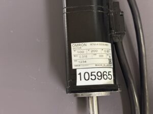
Technical Specifications – Omron R7M-A10030-BS1 Servo Mot
| Feature | Value | Note |
|---|
| Motor type | Omron R7M-A10030-BS1 | AC servo motor |
| Rated power | 100 W | according to nameplate |
| Rated voltage | 200 V | AC |
| Rated current | 0.87 A | |
| Rated torque | 0.318 Nm | |
| Rated speed | 3000 rpm | |
| Brake | Bremse Ogura MCNB 3.5Y-11 DC 24V | |
| Encoder | Yaskawa TRD-FY2000 | 2000 ppr, incremental |
| Manufacturer | Omron Corporation | Japan |
| Compatible servo drive | Omron R7D-AP01H Ver.22 | tested |
| Cooling | Self cooling | |
| Application | CNC axes, automation, material handling | |
Operating Environment and Compatible Equipment
The motor is typically used in compact CNC systems, pick and place units, packaging machinery and fast positioning modules.
Compatible drives include R7D-AP01H
The combination of an Omron motor with a Yaskawa incremental encoder is commonly found in older OEM automation equipment.
Functional Description
The R7M-A10030-BS1 is a precise AC servo motor with an external incremental encoder that provides position and speed feedback for closed loop control.
The drive R7D-AP01H processes A, B and Z signals, monitors signal integrity, phase alignment, encoder voltage levels and ensures accurate synchronization between mechanical motion and electrical feedback.
Safety features include overcurrent protection, encoder fault detection, thermal monitoring, undervoltage and overvoltage supervision and automatic power stage shutdown in the event of irregular feedback.
Alarm Messages and Troubleshooting
| Code | Description | Cause | Solution |
|---|
| A.C3 | Encoder disconnection detected | Open or shorted encoder wiring | Inspect cable, clean connector, replace encoder |
| A.C2 | Phase error | Incorrect electrical angle | Replace or realign encoder |
| A.C1 | Runaway detected | Invalid feedback during startup | Check wiring and encoder |
| A.51 | Overspeed | Missing or unstable pulses | Check encoder |
| A.04 | Parameter mismatch | Motor does not match driver | Load correct motor parameters |
| A.10 | Overcurrent | Short circuit or false feedback | Measure insulation resistance |
| A.40 | Over or undervoltage | Unstable 24 V supply | Check power source |
| A.d0 | Excessive deviation | Position counter overflow | Perform reference return |
| A.7A | Overheat | Mechanical overload | Inspect motor |
| A.bF | System error | Internal drive fault | Drive reset or replacement |