26.06.2025 by Viktor Siebert
Repair Process at Industrypart GmbH Mitsubishi Servo Drive MDS-DH-V2-2020
From Incoming Inspection to Final Commissioning – Using a Mitsubishi MDS-DH-V2-2020 Servo Drive as an Example.
A customer from the manufacturing sector contacted us with a simple but important question:
“Before I send in the device – can you explain exactly how your repair process works?”
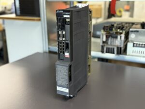
He was referring to a Mitsubishi Servo Drive, type MDS-DH-V2-2020, which suddenly showed no function at all – no display, no response, no status LED.
In this post, we explain step by step how our professional repair process works – transparent, systematic, and documented.
1. Incoming Inspection & Registration
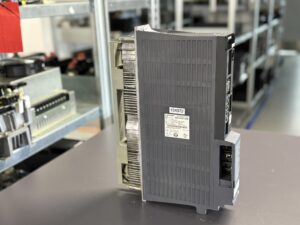
As soon as the device arrives at our facility, it is scanned, labeled with a QR code, and registered in our internal system.
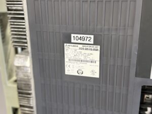
We inspect the packaging for damage and document any visible issues with photographs. Even if no documents are included, we identify the device based on the nameplate.
Example:
The MDS-DH-V2-2020 arrived without a delivery note, but the nameplate was legible. Packaging was intact, and no external damage was observed.
2. Visual Inspection & Initial Assessment
Our technicians begin with a detailed visual check:
- Are there signs of burning or heat damage?
- Are capacitors bulging or leaking?
- Are there cold solder joints or corrosion?
In the case of the MDS-DH-V2-2020:
During this step, we noticed a blown fuse in the internal power supply – a common sign of a short circuit in the intermediate circuit or power stage.
3. Electrical Diagnosis and Module Testing
Next, we conduct a comprehensive electrical diagnosis:
- Measuring the input and output voltages
- Checking gate drivers and IGBT bridges
- Analyzing the communication interface
- Simulating machine-like load conditions
We use manufacturer-specific testing setups, allowing us to test the unit even without the complete machine.
For the MDS-DH-V2-2020:
The internal power supply had completely failed – no 5V/15V output, no switching function. A defective driver IC was also identified.
4. Repair: Replacement & Restoration
Our technicians replace all faulty components using only high-quality or original parts. For safety-critical elements such as gate drivers, relays, or optocouplers, we prioritize OEM components.
For the MDS-DH-V2-2020:
- Replacement of several power semiconductors
- Repair of switching regulators
- New startup capacitors and driver ICs
- Reinforcement of high-load solder joints to extend lifespan
5. Functional & Load Testing
Once the repair is completed, the unit undergoes several rigorous testing stages:
- Cold start test (current draw, voltage levels)
- Machine simulation with test axes
- Long-term stress testing with varying load cycles
- Thermal analysis
In the case of the MDS-DH-V2-2020:
We simulated real-world CNC machine behavior using test motors and motion profiles. The device passed all stress tests without any anomalies.
6. Documentation & Quality Control
Before shipping, each repair is thoroughly documented:
- Fault description
- Actions taken
- Components replaced
- Test results
All records are archived digitally. A test report can be provided upon request.
7. Packaging & Return Shipping
The device is securely packaged using ESD protection and padded industrial cartons. Upon request, the customer receives a repair summary and test protocol.
We also offer express shipping and advance replacement services when available.
The MDS-DH-V2-2020 was returned with a complete report and passed tests within 5 working days.
Conclusion: Why Our Process Delivers Results
Repairs at Industrypart GmbH are not guesswork, but follow a precise and proven structure.
Especially for complex devices like the Mitsubishi MDS-DH-V2-2020, experience and component-level expertise are critical – especially when dealing with sensitive power supply and driver sections.
Our customer was not only satisfied with the end result but also appreciated the transparency and communication throughout the process.
To mentioned Mitsubishi Drive: Mitsubishi Servo Drive MDS-DH-V2-2020
More details about our Mitsubishi repair services can be found here:
Mitsubishi drive Repair by Industrypart
📞 Feel free to contact us with any questions about your Mitsubishi drive technology.
Our expert team is happy to help!
Device Description and Technical Data
Device Data (based on nameplate and manual)
| Parameter | Value |
|---|
| Model | MDS-DH-V2-2020 |
| DC Input | 3.2 A, DC 513–648 V |
| AC Input | 0.1 A, single-phase, 380–440 V or 480 V, 50/60 Hz |
| Output | 3.9 A / 3.9 A, 3-phase, 456 V, 0–240 Hz |
| Rated Power | 1.0 / 1.0 kW |
| Manual No. | IB-15000875 |
| Serial Number | J3AH8G2Y65X |
| Software Version | 1501W001 B1 |
| Hardware Version | Y |
| Production Date | 2014-11 |
| Manufacturer | Mitsubishi Electric Corporation, Tokyo 100-8310, Japan |
| Certifications | CE, TÜV, KCC, UL, TÜV SÜD, Type Approved, Safety Tested |
Internal Components
| Component Type | Markings on PCB | Qty |
|---|
| Control Board | RM115A-22 or BC886A028G51 | 1 |
| Power Board | RM162A-V2 or BC638A394G51CRM162C-V2 or BC886A010G52B/F | 1 |
| Power Stage (IGBT Unit) | BKO-NC1207 H84 or A2-DH-V2-2020 | 1 |
Typical Environment & Application
- Installed in: CNC machining centers (lathe, milling, drilling machines)
- Works with: Mitsubishi CNC control systems (M70, M700, M800 series)
- Motor types: AC servo and spindle motors (e.g. HF-KP, HF-SP, SJ-VL series)
- Installation site: Industrial control cabinets with temperature regulation
- Function: Provides regulated output to drive motors, manages encoder signals, ensures overcurrent/temperature protection
Alarms & Troubleshooting Table (excerpt)
| Alarm Code | Description | Reset Type | Recommended Action |
|---|
| 10 | Insufficient bus voltage | PR | Check DC supply, external contactor, input voltage |
| 17 | A/D converter error (feedback issue) | PR | Replace drive or check ambient conditions |
| 21 | No signal from sub-side detector (encoder) | PR | Inspect encoder cable and settings |
| 25 | Absolute position data lost | AR | Reinitialize zero point |
| 31 | Overspeed | PR | Review load, gear ratio, or parameter settings |
| 32 | Power module overcurrent | PR | Check for shorts in motor or cabling |
| 45 | Fan failure → thermal shutdown | PR | Replace fan and inspect heat sink |
| 71 | Instantaneous power interruption | NR | Check incoming AC quality, UPS, power supply |
Power Supply Alarms (selected)
| LED Display | Alarm Description | Reset Method | Action |
|---|
| 61 | Power module overcurrent in PSU | PR | Reduce motor load, check power components |
| 67 | Phase loss detected | PR | Verify phase wiring, power balance |
| 73 | Over-regeneration | NR | Let unit cool down (15 mins), check regen resistor |
| 75 | Overvoltage in DC bus | NR | Wait 5+ minutes before reset, review AC supply stability |