21.10.2025 by Viktor Siebert
Power Module Overheat in the Power Section Mitsubishi MDS-C1-SP-260 Spindle Drive Unit
Initial Condition and First Observations
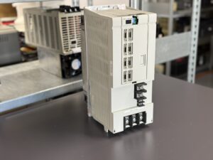
The Mitsubishi MDS-C1-SP-260 was sent to us with the fault “Power Module Overheat.” This alarm is quite common in the C1 spindle drives and almost always indicates a thermal imbalance in the power section. The unit came from an active CNC production line where it repeatedly shut down after a few minutes of operation. Externally, the module appeared to be in good condition, but experience shows that the visual appearance of these units says little about their actual internal condition.
Visual and Electrical Incoming Inspection
During the incoming inspection, the unit is first examined visually: condition of the connectors, fan, heatsink, insulation clearances, and any signs of overheating or dust deposits. This is followed by an initial electrical test without load. We measure the insulation resistance, check the DC bus voltage, and verify that the control section starts correctly. Already at this stage, typical irregularities can be detected, such as uneven current consumption or abnormal temperature rises around the heatsink area.
Test Run on the Test Bench
The actual diagnosis then takes place on our test bench, where we simulate real machine operation. The spindle drive is controlled by a CNC system and is subjected to defined ramps, acceleration, and braking cycles. During the test, all relevant signals are continuously recorded: DC bus voltage, phase currents, temperature curves, fan response, and brake chopper dynamics. The key point in a “Power Module Overheat” case is the timing correlation between temperature increase and current flow. If the temperature rises faster than can be explained by power dissipation, this indicates insufficient heat transfer or altered thermal characteristics in the power path.
Structured Disassembly and Module Inspection
Once this suspicion is confirmed, we begin with structured disassembly. The unit is divided into its main sections control, power, and cooling. Each section is cleaned and tested separately. In the power section, we focus especially on the components exposed to high thermal stress: power stage modules, gate drivers, thermal interfaces, sensors, and current paths. Testing is carried out under a microscope and supported by resistance and capacitance measurements.
Preventive Repair Approach
Instead of replacing individual components selectively, we consistently follow a preventive repair concept. This means that critical components known to age or change characteristics over time are replaced regardless of their current measurement results. This preventive package typically includes fans, thermal pads, heat transfer materials, connectors, selected electrolytic capacitors in the DC link, and optoelectronic components in the driver section. This approach ensures that the drive not only works again but also remains reliable for years to come.
Load Test and Functional Verification
After the overhaul, the drive is reassembled completely and subjected to a full-load test on the test bench. The test includes various scenarios: acceleration cycles, continuous thermal testing, regenerative braking simulation, and temperature measurements at several points in the power section. In parallel, current and voltage waveforms are recorded using an oscilloscope and data logger. The test runs for several hours and simulates realistic production conditions. Only when the drive delivers stable results under continuous load is it released for delivery.
Measurement Protocol and Quality Verification
At the end of the process, a measurement report is created documenting temperature curves, DC bus readings, phase currents, and communication status. This serves as proof of functional reliability and as a reference for future condition assessments if the drive is checked again.
Long-Term Reliability Through Preventive Refurbishment
The case of this MDS-C1-SP-260 clearly demonstrates why a systematic and preventive approach is essential. Many drives of this series have been operating continuously for over 15 years. Dust, oil mist, and thermal cycles gradually cause material degradation heat transfer interfaces lose their efficiency, fan performance drops, and capacitors age slowly. If only the immediate fault is repaired, the problem often reappears soon. When the entire system is refurbished, the machine remains stable in the long term.
Conclusion
Our philosophy is simple: every repair is also a technical renewal. We replace what has lost its reserves and test as if the device had just been manufactured. This creates long-lasting solutions that not only fix a failure but also prevent future ones. That is what distinguishes a repair from a simple fix and what makes the difference between temporary functionality and lasting reliability.
To mentioned Mitsubishi Drive: Mitsubishi MDS-C1-SP-260 Spindle Drive Unit
More details about our Mitsubishi repair services can be found here:
Mitsubishi drive Repair by Industrypart
📞 Feel free to contact us with any questions about your Mitsubishi drive technology.
Our expert team is happy to help!
Technical Specifications
| Parameter | Value |
|---|
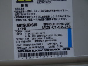
| Rated Power | 26 kW |
| DC Bus Input | 115 A, DC270–311 V |
| Control Supply Input | 0.2 A, 1-Phase 200–230 V, 50/60 Hz |
| Output Current | 97 A |
| Output Voltage | 3-Phase 200 V |
| Output Frequency Range | 0–833 Hz |
| Standard | DIN VDE0160 |
| Protection | approx. IP20 (for cabinet installation) |
| Cooling | Forced air (internal fan and heatsink) |
| Environment | 0–40 °C, clean and dry cabinet environment |
Note: Values were taken directly from the nameplate. Missing specifications are based on practical assumptions.
Connections
| Terminal | Description |
|---|
| L1, L2, L3 | 200 V 3-phase power supply via DC bus |
| P, N, DB | DC bus and brake resistor terminals |
| U, V, W | Spindle motor output |
| CN Control | Interface to CNC (Enable, Run, Analog, Digital I/O) |
| Encoder | Spindle feedback connection |
| PE | Protective earth terminal |
Assemblies
| Part Type | Model Number | Quantity |
|---|
| Control Board | RK311B-21 or BN634A817G51 C, alternatively RK311C-21 or BN638A170G51 | 1 |
| Power Driver Board | RL125A-SP-300 or BN638A138G51 D | 1 |
| Power Module Section | BKO-NC1208 H90 or B1-SP-260 | 1 |
| Fan Unit | Axial fan 24 V, 2-wire | 1 |
| Heatsink | Extruded aluminum profile with temperature sensor | 1 |
| Protection/Measurement Section | Shunts, thermal sensor, gate driver, snubber | – |
Functional Description
The SP drive converts the DC bus voltage into a variable three-phase output voltage and frequency. The internal control includes current, speed, and position loops managed by the CNC. During deceleration, the regenerative energy is returned to the DC bus and dissipated through the braking resistor. Thermal sensors continuously monitor the heatsink temperature and power components to prevent overheating.
Common Alarms and Causes
| Display | Description | Cause | Remedy |
|---|
| 3B | Power Module Overheat | Heatsink temperature too high, insufficient airflow, worn or blocked fan | Check and replace fan, clean heatsink, verify heat transfer and cooling path |
| OC | Overcurrent | Overcurrent in the power section, short circuit at the motor or output stage | Inspect motor and cabling, test power stage, perform insulation check |
| OV | Overvoltage | DC bus voltage too high, regeneration or brake circuit issue | Check brake resistor, brake chopper, and input power quality |
| UV | Undervoltage | Supply voltage too low or unstable | Check power input, measure and replace DC link capacitors if needed |
| OH | Heatsink Overheat | Heatsink temperature exceeds threshold | Verify fan operation, clean air filters, ensure proper airflow |
| GF | Ground Fault | Ground fault detected in the motor circuit | Measure insulation resistance, check motor cable and connections |
| OL | Overload | Spindle overloaded or mechanically jammed | Reduce load, check parameters and mechanical system |
| 32 | Power Module Overcurrent | Overcurrent in power module, internal short or switching fault | Inspect power section, measure insulation, check internal circuits |
| 77 | Power Module Overheat (IPM) | Power module thermal protection activated | Clean heatsink, replace fan, renew thermal interface materials |
| COM | Communication Error | CNC communication interrupted or unstable | Check CNC interface, control board, and signal cables |