18.11.2025 by Viktor Siebert
Repair of a Fanuc A06B-6117-H303 with a DC Bus Short Circuit on the M Axis
When the Fanuc A06B-6117-H303 Servo Drive Unit arrived at our workshop, the error was already clear: The machine shut down immediately after servo power-up, accompanied by the alarm “DC Bus Overcurrent”. The customer reported that the machine stopped during a rapid movement and had not been able to restart since. Even the first visual inspection provided a clear direction. On the right side of the heatsink in the M-axis section, slight discolorations were visible, typical of thermal overload in the power device. Based on these visual indicators, it was reasonable to assume an internal short circuit within the IGBT module.
The first step was complete disassembly of the unit. After separating the DC bus and output stages, the power device block of the M axis was exposed. Here, the suspicion was confirmed: One of the three half-bridge sections showed visible thermal damage. The insulation layer of the IGBT module had dark markings and signs of heat impact. Such damage is usually caused by internal breakdowns between collector and emitter or by incorrect gate control under high load variations. Since the A06B-6117-H303 uses a shared DC bus, a short on one axis will immediately shut down the entire drive.
Next, all traces around the DC bus input were examined. Special attention was given to the shunt resistors, which handle precise current measurement in the Fanuc drive. These components are essential for proper operation of the protection circuits. The gate driver board was also thoroughly inspected, as driver components are frequently affected by IGBT short circuits. In this case, one driver channel of the M axis showed increased leakage currents, a typical sign of secondary failure.
After the diagnosis, we replaced the entire power module of the M axis. Only high-quality replacements with matching electrical and thermal ratings were used. In parallel, the damaged driver components were repaired. The unit was then cleaned thoroughly, the heatsink was cleared of dust, and new thermal paste was applied to ensure optimal heat transfer.
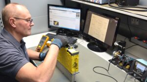
The subsequent testing took place on our CNC test stand using a compatible αi-BL motor. The drive was first tested under low load, then gradually subjected to increasing mechanical and thermal load. Over several hours, the unit was run under full operating conditions while all parameters DC bus voltage, phase currents, PWM signals, temperature sensors were monitored and logged. The drive remained stable without any abnormalities.
Through precise diagnostics and targeted replacement of the critical components, the drive was restored to full working condition. The customer received a completely refurbished unit including detailed documentation and test reports.
Preventive Measures
- Regular cleaning of the airflow channels
- Fan replacement every 3–4 years
- Monitoring DC bus for voltage drop or ripple
- Axis mechanics inspection when currents rise
- Thermal monitoring of high-dynamics axes
- Visual inspection of the heatsink area
Conclusion
A DC bus short can shut down an entire servo amplifier. With professional diagnostics, targeted repair and extensive testing, Fanuc drives can be restored reliably and their lifetime significantly extended.
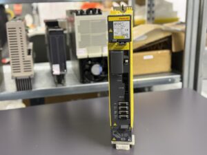

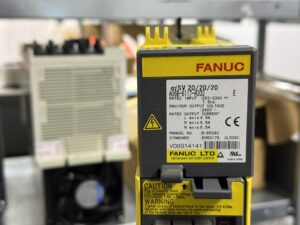
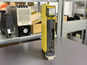
To mentioned Fanuc Drive: Fanuc A06B-6117-H303 Servo Drive Unit
More details about our Fanuc repair services can be found here:
Fanuc drive Repair by Industrypart
📞 Feel free to contact us with any questions about your Fanuc drive technology.
Our expert team is happy to help!
Device Description
| Parameter | Value | Note |
|---|
| Model | A06B-6117-H303 | Fanuc αiSV 20/20/20 |
| Axes | 3 (L, M, N) | approx. 6.5 A each |
| Input | DC bus from PSM | approx. 283–325 V DC |
| PSM supply | A06B-6114-H0xx | external supply |
| Output power | approx. 3 × 2 kW | depending on motor |
| Weight | approx. 7.5 kg | model dependent |
| Control | Fanuc CNC 30i / 31i / 32i | compatible |
| Cooling | Forced air | heatsink + fan |
| Protection | Overcurrent, overvoltage, overheat | per Fanuc |
| Manual reference | Fanuc Alarm Manual B-65285E | |
| Design | Servo amplifier module | αi series |
Operating Environment & Compatible Devices
The Fanuc A06B-6117-H303 Servo Drive Unit is used in CNC machine tools, typically:
- Vertical machining centers
- Horizontal machining centers
- Gantry and grinding machines
- Precision axes with αi-series BL motors
Compatible motor families:
- Fanuc αi-BL (e.g. αiS8/3000, αiS12/4000)
- Fanuc αi-BHV, depending on the machine
- Encoder types: αi-A, αi-B, αi-C incremental and absolute
The drive operates from the shared DC bus of the PSM module and controls L, M and N axes.
Functional Description
The Fanuc A06B-6117-H303 Servo Drive Unit is a triple-axis amplifier that controls motor currents precisely and processes the motor feedback. All axes are supplied through the shared DC bus.
The drive performs the following functions:
- Current control for each axis
- Speed control
- Position feedback processing
- Protection routines such as overcurrent, overheat, overvoltage
- Communication with the CNC via the Fanuc Servo-Link interface
- Energy supply via the DC bus from the PSM
Due to the shared DC bus architecture, a failure on one axis (such as the M axis) can stop the entire amplifier.
Alarm Messages & Troubleshooting
| Code | Description | Cause | Solution |
|---|
| Alarm 01 | Power Supply Unit Error | PSM fault, undervoltage | Check PSM, measure DC bus |
| Alarm 02 | Converter Link Error | Communication fault | Check link cable |
| Alarm 03 | Inverter DC Bus Voltage Error | Overvoltage or undervoltage | Check DC bus |
| Alarm 04 | Motor Power Line Overcurrent | Short circuit, power device fault | Check IPM/IGBT |
| Alarm 05 | Inverter Overheat | Insufficient cooling | Clean fan/heatsink |
| Alarm 06 | Inverter Overload | Axis overload | Check mechanical axis |
| Alarm 10 | Encoder Communication Error | Encoder fault | Inspect cable/encoder |
| Alarm 12 | Encoder Initialization Error | Start-up failure | Reinitialize encoder |
| Alarm 14 | Shaft Encoder Initialization Error | Axis encoder fault | Replace encoder |
| Alarm 20 | Motor Overheat | Excessive motor heat | Check motor/load |
Components
| Component | Model Designation | Function | Notes |
|---|
| Control Board | A20B-2101-0042 10F | Main control and communication PCB | Responsible for regulation, communication and internal logic |
| Control Board | A20B-2101-0042 11G | Alternative or revised version of the control PCB | Compatible within defined production revisions |
| Power Board | A16B-2203-069 8/09B | Main power module for axes L/M/N | Contains gate drivers, measurement stages and power transfer paths |
| Power Module | Power Module | Three-phase power section for the axes | Includes IGBT/power devices and DC bus interface |