13.11.2025 by Viktor Siebert
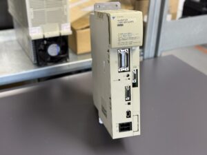
Repair of a Yaskawa CIMR-MXN25P5 Inverter Unit with Alarm 20 Motor Over Current
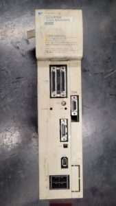
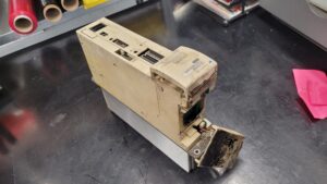
The returned unit showed Alarm 20 Motor Over Current immediately after power-up. During the initial inspection, it was determined that the internal fan had completely failed. This caused heat accumulation in the power section, leading to uneven thermal stress across the IGBT modules. The internal current sensor detected an increasing power loss and correctly activated the overcurrent protection circuit.
Following the diagnostic assessment, the inverter was fully disassembled into its functional assemblies: control board, communication card, power board, and power section. Each assembly was thoroughly cleaned, all connectors were ESD-treated, and components were checked for aging or wear.
At industrypart GmbH, repairs are not limited to replacing failed components. Every inverter undergoes a preventive overhaul, ensuring long-term operational reliability. During the repair of this unit, the following parts were replaced or renewed preventively:
- Fan unit replaced with a new low-noise model offering identical airflow and vibration-free bearings.
- DC bus capacitors all 400 V electrolytic capacitors were replaced to eliminate aging effects and capacity loss.
- Precharge circuit components (relay and resistor) replaced as a preventive measure due to thermal stress over time.
- Gate driver components aged optocouplers replaced to maintain clean IGBT gate switching behavior.
- Temperature sensors checked for correct response curve; replaced where deviation was detected.
- Solder joints and copper traces reflowed in all areas of the power board YPCT31448-1B exposed to thermal cycling.
After the overhaul, the unit was electrically reassembled and tested for isolation resistance and continuity. Functional and load testing was then performed on the company’s Yaskawa STAR test bench, which simulates a real Siemens-Yaskawa CNC environment. The inverter was operated in a closed control loop with a test motor while current waveforms, voltage levels, temperature, fan operation, and protection triggers were continuously monitored and recorded.
During the several-hour endurance run under full load, the inverter showed completely stable performance:
- The DC bus voltage remained constant within nominal limits.
- The three-phase output currents were balanced and symmetrical.
- Heatsink temperature stabilized below 55 °C.
- All protection circuits reacted correctly during simulated fault conditions.
A final inspection was carried out according to the internal checklist, including optical control, insulation measurement, thermal imaging analysis, and quality approval. The device was documented, sealed, and released for customer use.
Through the preventive replacement of all critical and time-sensitive components, the inverter’s reliability was not only restored but brought back to the standard of a factory-refurbished unit. This procedure significantly extends service life and minimizes the likelihood of future downtime.
The Yaskawa CIMR-MXN25P5 now operates again with optimal thermal balance, stable current regulation, and high reliability in continuous industrial use.
Preventive Measures for the Customer
| Action | Interval | Benefit |
|---|
| Fan replacement | Every 2–3 years | Prevents overheating and protects IGBT modules |
| Cleaning of heatsink and air filters | Semi-annually | Ensures proper airflow and cooling |
| Check terminal connections (R-S-T / U-V-W) | Annually | Prevents loose connections and heating |
| Insulation test of motor cables | Annually | Detects cable degradation early |
| Visual inspection of circuit boards | During maintenance | Detects corrosion or discoloration |
| Retightening mechanical fixtures | Annually | Prevents vibration damage and cracking |
Summary
The Yaskawa CIMR-MXN25P5 was fully refurbished with a preventive replacement of all critical components, including fan, DC capacitors, precharge circuit, and gate drivers.
The inverter successfully passed all full-load tests on the Yaskawa STAR test bench and is now operating within specification.
The combination of preventive overhaul and structured testing ensures factory-level reliability and long-term stability for demanding CNC applications.
Further information such as price and delivery time for:
Yaskawa CIMR-MXN25P5 Inverter Unit
More details about our Yaskawa repair expertise can be found here: Yaskawa Reparatur bei Industrypart
📞 Please feel free to contact us if you have any questions regarding your Omron drive technology. Our experienced team is always available to assist you.
Device Data
| Specification | Value | Remark |
|---|
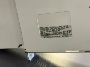
| Manufacturer | Yaskawa Electric Corporation | Made in Japan |
| Model designation | CIMR-MXN25P5 | MXN series (Vector-Control Inverter) |
| Device type | AC inverter / frequency converter | For CNC and machine tool applications |
| Series code / Spec | 25P55B | 200 V class |
| Input power | DC 270 – 325 V (equivalent to 3-phase 200–230 V AC) | Rectified input |
| Output power | 0 – 230 V AC, 3-phase, 0–1000 Hz | Motor supply |
| Rated current | 19 A (50% ED 29 A max.) | According to nameplate |
| Output current | 20 A (50% ED 34 A max.) | |
| Rated power | 5.5 kW | Continuous operation |
| Weight | approx. 4.0 kg | Compact design |
| Cooling | Forced air cooling (DC axial fan) | Replacement interval approx. 2–3 years |
| Control method | Vector control / PWM modulation | CNC integration with Siemens-Yaskawa systems |
| Protection functions | Overcurrent, overheat, undervoltage, overvoltage, ground fault, phase loss | Multi-stage protection system |
| Manual reference | Yaskawa VARISPEED 626 M5 / 656 MR5 User Manual | Chapter 12 “Converter Faults” |
Operating Environment & Compatible Equipment
| Parameter | Description |
|---|
| Typical applications | CNC machines, tool changers, feed axes, spindle control |
| Control systems | Siemens-Yaskawa combined CNC controllers |
| Compatible motors | Yaskawa AC motors, 3-phase 5.5 kW / 200 V |
| Ambient temperature | 0 – 40 °C (non-condensing) |
| Humidity | 20 – 80 % RH |
| Mounting style | Control cabinet installation (IP20) |
| Cooling | Forced ventilation over heatsink fins |
| Special requirements | Avoid dust and oil mist, ensure sufficient airflow |
| Test environment | Yaskawa STAR test bench with Siemens-Yaskawa control system (closed-loop operation) |
Functional Description
The Yaskawa CIMR-MXN25P5 is a compact, vector-controlled frequency inverter designed for precise speed and torque control of AC motors.
It converts three-phase input voltage into a regulated DC bus and generates three PWM-modulated phase outputs.
A microcontroller governs the vector and current control, while temperature sensors, shunt resistors, and gate drivers continuously monitor and protect the power stage.
Integrated protection circuits respond to overcurrent, thermal overload, phase failure, or voltage irregularities.
Alarm 20 – Motor Over Current is triggered when the output current exceeds the threshold, typically caused by motor short circuits, load surges, or thermally stressed transistors.
Alarm Messages & Troubleshooting
| Code | Description | Cause | Corrective Action |
|---|
| 01 | Overcurrent | Short circuit or excessive motor load | Check motor cable, perform insulation test |
| 02 | Overvoltage | Excessive DC bus voltage | Check input voltage and braking resistor |
| 03 | Undervoltage | Input voltage too low | Check power supply and wiring |
| 05 | Overheat | Heatsink temperature too high | Check fan operation and airflow |
| 07 | Control Power Fault | Control supply unstable | Check SMPS secondary voltage |
| 09 | Ground Fault | Ground fault at motor output | Test insulation of motor cable |
| 11 | Motor Overload | Continuous overload condition | Reduce load, verify cooling and fan |
| 13 | Output Phase Loss | Missing phase or power stage defect | Check output cabling and IGBTs |
| 20 | Motor Over Current | Overcurrent at U/V/W phase output | Inspect cooling, IGBT, motor, and fan |
| 22 | Thermistor Fault | Temperature sensor defective or open | Replace thermistor or repair connection |
Components
| Type | Board marking | Function | Quantity |
|---|
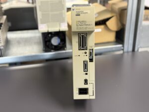
| Control board | SGDK-CAS01LA-V 0038 Rev.A0 or DF0300545-A0 | Central control and signal processing, PWM generation, communication interface to CNC | 1 |
| Communication / Option card | SGDK-CF01A-V Rev.B0 or DF0300130-B0 | Expansion and interface board for external communication or CNC data exchange | 1 |
| Power board | YPCT31448-1B | DC bus section with gate control, precharge circuit, current sensing and protection circuits | 1 |
| Power module | Main power section (IGBT module + heatsink + fan) | Converts PWM control into 3-phase output, core energy path of the inverter | 1 |