11.11.2025 by Viktor Siebert
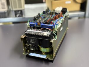
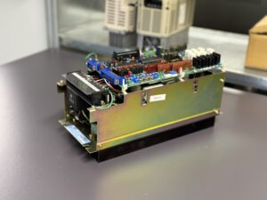
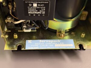
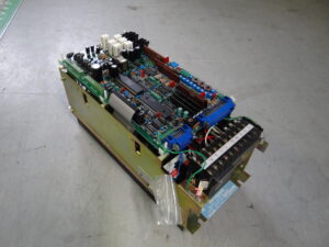
Repair of a Yaskawa CACR-SR20SB1BFY100 with Output Short Circuit
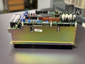
The CACR-SR20SB1BFY100 arrived at our workshop with a clear report: “Output W shorted.” During the initial inspection, a direct low-resistance path was detected between the W terminal and the DC bus an unmistakable sign of an internal short circuit in the power module. Upon opening the housing, the 6DI75A-050 transistor block was found destroyed on one leg of the bridge.
Before replacing such a component, a structured diagnostic process is essential. A simple swap can overlook other faults like defective gate drivers or damaged resistors in the control stage.
The repair process began with a step-by-step electrical analysis:
- Insulation test of the output path to exclude residual shorts.
- Gate signal verification using differential probing to ensure timing integrity.
- DC-link charge control test to evaluate transient behavior.
After replacement of the defective module, the DC-link was recharged gradually through a current-limited supply. Temperature sensors monitored the thermal load during each start sequence. Only after several controlled charge-discharge cycles was the unit connected to a test motor.
This stage is crucial: older analog Yaskawa drives can exhibit offset or phase imbalance after repair, potentially destroying the new power stage.
Hence, the device underwent multi-level testing:
- No-load run under simulated load to verify regulation loop stability.
- Extended runtime test (4+ hours) at up to 50°C ambient temperature.
- Phase analysis using oscilloscope to check waveform symmetry and noise margin.
After a successful four-hour thermal run, the drive showed perfect current symmetry and stable operation. A final verification followed with an original Yaskawa motor, confirming precise control response and zero drift at low speed.
Testing during and after repair is not a formality it is the foundation of quality assurance. Every recorded measurement builds confidence that the repaired unit will perform reliably in continuous operation.
This project demonstrated once more: true repair quality is measured in testing discipline, not in replaced parts.
Preventive Maintenance Recommendations
| Measure | Interval | Benefit |
|---|
| Clean PCBs and housing | Every 12 months | Prevents leakage current |
| Inspect and reseat connectors | Quarterly | Ensures stable signal contact |
| Check cooling and air path | Annually | Prevents thermal stress |
| Insulation test (motor & cables) | Yearly | Early detection of breakdowns |
| Measure DC-link voltage | During maintenance | Monitors power supply stability |
| Record all test data | Continuous | Provides baseline for future servicing |
Conclusion
Repairing a Yaskawa CACR-SR20SB1BFY100 requires both technical precision and patience. Only by testing continuously before, during, and after repair can the reliability be restored. Each measurement verifies that the device is safe, stable, and ready for long-term operation. In our experience, testing is the real key to quality.
To mentioned Yaskawa Drive: Yaskawa CACR-SR20SB1BFY100 Servopack
More details about our Yaskawa repair services can be found here:
Yaskawa drive Repair by Industrypart
📞 Feel free to contact us with any questions about your Yaskawa drive technology.
Our expert team is happy to help!
Technical Specifications:
| Specification | Value | Comment |
|---|
| Manufacturer | Yaskawa Electric | Japan |
| Device Type | AC Servo Drive (Servopack) | Analog control, single-axis unit |
| Model | CACR-SR20SB1BFY100 | VS-800 Series |
| Rated Power | 2.0 kW | Derived from “20” in the model code |
| Operating Voltage | 3-phase, 200 V AC | 50/60 Hz |
| Control Type | Analog | ±10 V reference input |
| Axis Count | 1 | Single axis |
| Cooling | Convection cooling | Passive, fanless |
| Weight | Approx. 5.5 kg | Depending on revision |
| Compatible Motors | USAGED, USASEM, USAME Series | Yaskawa Servomotors |
| Status | Discontinued (EOL) | Available only through repair |
| Manual Reference | Yaskawa TSE-S800-2.1J | AC Servo Drive M.F.S.D Series |
Application Environment & Compatible Devices
The CACR-SR20SB1BFY100 is part of the Yaskawa VS-800 series, widely used in machine tools, CNC feed axes, and robotics applications. It typically drives motors from the USAFED or USAMED families, using analog velocity control signals. These units often operate in conjunction with YASNAC control systems, where reliability and precise torque control are critical.
The construction is robust, with discrete transistor drivers and analog control circuits. Despite their age, these drives are known for exceptional stability and precision, provided they undergo regular testing and maintenance.
Functional Description
This Servopack regulates the motor’s torque and speed via an analog ±10 V input. Inside, it integrates multiple protection and regulation functions: overcurrent, overvoltage, overheat, dynamic braking, as well as closed-loop feedback control for torque and speed.
The main power circuit is switched by a transistor module 6DI75A-050, which delivers power to the three phases U, V, and W.
Protective logic responds within milliseconds to excessive current. A failure on one output phase like the short circuit on “W” in this case immediately triggers shutdown and protective isolation. Without detailed testing, restarting such a unit can easily result in cascading damage.
Alarms & Troubleshooting
| Code | Description | Cause | Solution |
|---|
| 01 | Overcurrent | Output short circuit or damaged transistor module | Inspect and replace the power module |
| 02 | Control Power Fault | ±12 V supply failure | Check internal power supply |
| 03 | Overheat | Heatsink temperature too high | Clean and inspect cooling path |
| 05 | Motor Overload | Continuous overcurrent | Check load torque and mechanical friction |
| 07 | Input Power Error | Supply voltage instability | Verify mains input and wiring |
| 09 | Encoder Error | No position feedback | Inspect encoder cable and sensor |
| 11 | Gate Signal Error | Driver stage malfunction | Check driver board |
| 13 | Inverter Bridge Error | Power transistor shorted | Replace power module |
| 20 | CPU Loop Error | Control logic malfunction | Retest after replacement |
| 25 | Control Command Error | Invalid input or noise | Verify reference signal integrity |
Components
| Component | Part / Code | Function | Inspection Notes |
|---|
| Power Module | 6DI75A-050 | Six-transistor IGBT pack | Check insulation and phase short |
| Control PCB | CACR-SR-B1BF | Drive logic and analog control | Inspect for cold joints |
| Power Supply Board | ±12 V, DC-Link | Provides auxiliary voltages | Check ripple with oscilloscope |
| Output Section | U/V/W phases | Motor output stage | Verify waveform symmetry |
| Signal Interface | CN1 / CN2 | Command and feedback connectors | Clean and reseat contacts |